Table of Contents
Advertisement
Quick Links
Advertisement
Table of Contents

Summary of Contents for ClimaCheck NX400
- Page 1 ClimaCheck Gateway NX400 Hardware Manual Updated for Application v3.00 2020-03-26 ClimaCheck Sweden AB, Box 46, SE-131 06 Nacka, Sweden Visiting address: Gamla Värmdövägen 6, SE-131 37 Nacka Sweden Tel.: +46 (0)8-50 255 250, Email: info@climacheck.com Web: www.climacheck.com...
-
Page 2: Safety Precautions
In many cases the value of products or cost of production loss represents great values. ClimaCheck do not assume any responsibility for injuries or costs occurring if failures are caused in connection with measurements. It is the user that must evaluate if an installation can be carried out without risks to cause injuries and/or damage. -
Page 3: Table Of Contents
Analog Input Mode selection switches (mA/V) ............35 Network interface selection switch ................35 Digital inputs ......................36 A and B alarms to digital out ................... 36 External connections ....................37 Modbus RS485 terminal ..................40 ClimaCheck Gateway NX400 Hardware Manual – 2020-03-26 Page 3 of 41... -
Page 4: Overview
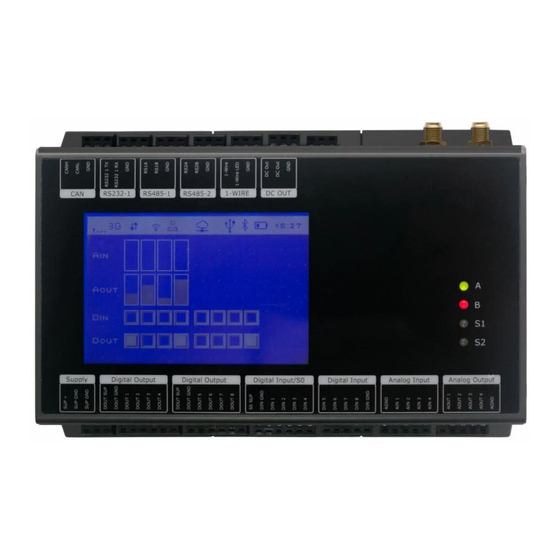
1 Overview On the front of the ClimaCheck Gateway NX400 unit a display, 4 LEDs and the reset button can be found. Figure 1 Front view of ClimaCheck Gateway NX400 1.1 LED indicators The ClimaCheck Gateway NX400 has 4 LED indicators: •... - Page 5 1-Wire communication error (see display for additional information) Off (Red) On (Red) Alarms active in the Easycool controller, see alarm page on ClimaCheck Online (Yellow) When the Modbus or 1-Wire communication alarm is active, address and name of the unit can be seen in the display.
-
Page 6: Display
Flashing (Yellow) 1.2 Display On the front of the ClimaCheck Gateway NX400 unit a 240x160 pixel, withe on blue, LCD display with built in resistive touch sensing can be found. The top part of the display is reserved for a status bar showing status of the different... - Page 7 RTCU Gateway Status RTCU Gateway not enabled RTCU Gateway enabled RTCU Gateway connected USB status USB host supported Bluetooth status Bluetooth off Bluetooth on Power status Battery level (animated while charging) ClimaCheck Gateway NX400 Hardware Manual – 2020-03-26 Page 7 of 41...
-
Page 8: Climacheck Gateway Nx400 Internal Application Version And Pa-Id
Each Gateway unit has a unique id number to identify it on the ClimaCheck Online server, this number is set by ClimaCheck and can be seen in the display, on the second row, after the unit has booted up as “ID=XXXXXX”. -
Page 9: Communication
2 Communication The Gateway has LAN, Wifi, modem for Mobile connections and USB to communicate with the ClimaCheck server or a local PC. It has Modbus TCP and Modbus RTU and can be configured both as Server/Slave and Client/Master. 2.1 Ports The Gateway uses the following ports when communicating with the ClimaCheck Online server: •... -
Page 10: Connection Mode
NX400. First option is USB Cable / WiFi and second option is Direct ethernet cable between computer and NX400, see Figure 4 and section 2.4 for more information on how to connect a PC. If no selection is made the unit activates Online Mode or PC Mode (USB Cable / WiFi) automatically depending on the default setting. -
Page 11: Pc Connection
The Gateway can be setup to activate the modem and try to connect and establish a GPRS (Modem) connection with the ClimaCheck Online server if a SIM-card is inserted in the unit. If activated, this is done for both Connection Modes (Online and PC) and regardless of network interface settings except “No Network”, see section 3.11. - Page 12 Figure 5, Direct connection to PC ClimaCheck Gateway NX400 Hardware Manual – 2020-03-26 Page 12 of 41...
-
Page 13: Climacheck Gateway Nx400 Internal Application
3 ClimaCheck Gateway NX400 internal application The chapter describes functions in the internal application of the ClimaCheck Gateway NX400 that are accessible through the display on the unit. 3.1 Menu structure The menu structure is shown in the figure below. To open a sub menu press the SEL button, to choose a function or confirm a configuration OK button is used. -
Page 14: View All Values
Figure 7, “View all values” menu 3.3 Send interval / Intense send When ClimaCheck Online is used data is sent to the ClimaCheck server once every minute when the compressor is on and every 5 minutes when the compressor is off. To activate “intense send”... -
Page 15: Show Ip-Addresses
Description IAIO Internal Analog Input and Output on the Gateway R560 ClimaCheck R560 analog input module PScout Power Scout power meter Internal 1-Wire module Figure 8, "Show IODevices" menu ClimaCheck Gateway NX400 Hardware Manual – 2020-03-26 Page 15 of 41... -
Page 16: 1-Wire Temperature Sensors
+ 0.5m per sensor + 0.5m per split. Weight = total cable length + 0.5*sensor + 0.5*split Example: 3 sensors on 2 meter stubs that is located 5 meters from the NX400 with 1 split has a total weight of 0.5*3+(2*3+5)+0.5*1=14. - Page 17 Press ESC 4 times to go back to the main menu or start from the top to connect another sensor. If “No new s-r found” appears while setting up a new sensor the NX400 cannot find any sensor on the bus that is not already configured, check connection and make sure the sensor has not been connected already.
-
Page 18: Reboot And Reload Configuration
NX400 has lost connection with the sensor, check wiring. 3.8 Reboot and Reload Configuration Most of the configuration for external units can be done on the ClimaCheck server. Changes to Modbus addresses for external units such as energy meters or R560 modules can be done on the ClimaCheck Online server and then downloaded to the unit. -
Page 19: Wifi Connectivity For Pc In Online Mode
• Press ESC until the start screen shows A PC can now connect to the NX400 and log data over WiFi simultaneously as data is sent to ClimaCheck Online. To deactivate the access point functionality again follow the steps below. -
Page 20: Gprs (Modem) In Pc And Online Mode
Data can be saved to a USB memory connected to the USB-port on the top side of the unit, see Figure 31. Data is saved with the same interval that is used to send data to the ClimaCheck Online server i.e. once every minute when the compressor is running and every 5 minutes when it’s off. -
Page 21: Backup Configuration To Usb Memory
Press SEL to enter USB/Backup menu • Press down until “Backup/Restore config” appears in the display • Press SEL to enter menu • Press “Backup intern” and confirm with OK ClimaCheck Gateway NX400 Hardware Manual – 2020-03-26 Page 21 of 41... -
Page 22: Load Configuration From Usb Memory
Press SEL to enter USB/Backup menu • Press down until “Backup/Restore config” appears in the display • Press SEL to enter menu • Press “Restore from Intern” and confirm with OK ClimaCheck Gateway NX400 Hardware Manual – 2020-03-26 Page 22 of 41... -
Page 23: Pa Pro Iii Configurator
The ClimaCheck Gateway NX400 configuration tool can be found under the Performance Analyser Pro menu in the ClimaCheck software. To use the PA Pro III Configuration tool the computer needs to be connected with a USB cable. Ethernet or Wifi connection will not work. -
Page 24: Password Protection
IO Config Edit Handles configuration for analog inputs on the Gateway and external units connected through Modbus/RS485. Data send interval, interval to fetch commands from the ClimaCheck Online server and Debug mode is also controlled from this tab. Mobile APN, username and other settings for the built-in modem. -
Page 25: Adjust Clock
4.3 Adjust Clock The internal clock is synced with the ClimaCheck online server with the correct time zone of the unit. However, if unit has been moved, the clock can be set from the Action menu. • Connect to and unlock the device with present password, see 4.2.1 •... -
Page 26: Configuration Files
Figure 15, Firmware update 4.4.2 Update Application If both Firmware and Application files are supplied by ClimaCheck support start with the Firmware files and then the Application files. The application is supplied as a compressed file with a folder inside. Extract the folder to a place on your computer and then: •... -
Page 27: Edit Gateway Input Configuration
4.5.2 Open and make a backup of the Gateway NX400 configuration To open the present configuration and save it to a file follow the steps below • Connect to and unlock the device with present password, see 4.2.1 • On the IO Config Edit tab go to Edit Device and then Open Configuration in device The configuration is loaded and all settings are displayed on the IO Config Edit tab. - Page 28 Download configuration from ClimaCheck Online server over internet Contact ClimaCheck support and make sure the correct configuration is updated on the server then see section 3.9. Load new configuration from a configuration file (*.CFG) Contact ClimaCheck support to get a configuration file with the new external device included then see section 4.5.3.
- Page 29 Param 1 - Limit for no operation (kW), see section 4.7.2 EM24 / EM26 Param 2-10 – n/a EM24 / EM26 Param 1 - Limit for no operation (kW), see section 4.7.2 no voltage Param 2-10 – n/a ClimaCheck Gateway NX400 Hardware Manual – 2020-03-26 Page 29 of 41...
- Page 30 Param 2 – Number of registers to read (Master) Param 3-10 – n/a MB 16Bit in See ClimaCheck_NX400_ModBusRTU_TCP manual. storage MB 16Bit out See ClimaCheck_NX400_ModBusRTU_TCP manual. storage MBTCP16bit See ClimaCheck_NX400_ModBusRTU_TCP manual. (Client) ClimaCheck Gateway NX400 Hardware Manual – 2020-03-26 Page 30 of 41...
-
Page 31: Communication Settings
MB RTU Slave Address sets the address used when the unit is configured as Modbus Slave. The port used will automatically be selected as the port not used as master interface. It is also possible to set the communication parameters for the Modbus RTU. See separate NX400 - Modbus RTU Slave manual for details. -
Page 32: Mobile Tab
Apply button. Figure 21 Mobile tab and PIN Code window Default settings with APN for the SIM card provided by ClimaCheck can be seen in Figure 21. To use a different SIM-card follow the instructions below. -
Page 33: Lan 2 Tab
Figure 22 LAN 1 tab 4.10 LAN 2 tab LAN 2 tab contains settings for the second network connection through a USB-to-Ethernet converter, not included as standard. See section 4.9 for configuration or contact ClimaCheck for more information. 4.11 WiFi tab WiFi tab contains settings for the WiFi connection used for Internet access. -
Page 34: Gateway And Pcmode Tab
Firmware and internal application in the Gateway can be remotely updated through the ClimaCheck RTCU gateway. Do not change settings if not instructed to do so by the ClimaCheck Support. PC Mode The default communication mode described in section 2.3 can here be configured as PC Mode (tick the box) or Online Mode (no tick in the box), see Figure 24. -
Page 35: External Switches And Connections
5 External switches and connections The chapter describes the external connections and DIP-switches on the ClimaCheck Gateway NX400. For a full description please refer to the supplier manual RTCU-NX400. 5.1 Analog Input Mode selection switches (mA/V) To change the analog inputs on the Gateway between current and voltage input dipswitches on the back side of the unit is used, see Figure 25. -
Page 36: Digital Inputs
(DINx) and the DIN GND on the corresponding terminal connector group. 5.4 A and B alarms to digital out Alarms set on ClimaCheck online server can be categorised as A or B alarms and digital out 7 or 8 can be activated. -
Page 37: External Connections
Above the terminal blocks the following interfaces are found: SMA connector for UMTS/GSM, RP- SMA connector for Wi-Fi / Bluetooth, USB host port, Ethernet connector, RS232 port and finally DIP-switches. ClimaCheck Gateway NX400 Hardware Manual – 2020-03-26 Page 37 of 41... - Page 38 Figure 31 Top-side view Below is a list of the pin numbers and descriptions. The pins relevant to ClimaCheck application are highlighted in yellow. Table 7 Name Description SUP+ Power supply, positive (+) connection SUP GND Power ground, negative 1 (-) connection...
- Page 39 DCOUT +5V / 300mA DC-OUT for external equipment (tied together internally) Signal ground External battery positive (+) connection External battery negative (-) connection External battery NTC temperature sensor connection ClimaCheck Gateway NX400 Hardware Manual – 2020-03-26 Page 39 of 41...
-
Page 40: Modbus Rs485 Terminal
Gateway, see Figure 32. Figure 32, RS485 terminals on NX400 For the portable ClimaCheck Onsite PA Pro III, the RS485-1 is connected to a D-Sub contact in the panel, see Figure 33. Connections to RS485-2 is done directly to the screw terminals. - Page 41 1,2,6,7,8 and 9 in Figure 33 above. If using communication cables other than supplied by ClimaCheck make sure that these not risk short circuiting the connection. If 24VDC is supplied to any of the RS485 connections they will be damage.
Need help?
Do you have a question about the NX400 and is the answer not in the manual?
Questions and answers