Table of Contents
Advertisement
Quick Links
SPECIAL LANGUAGE DEFINITIONS
The following terms are used throughout the product literature to indicate
various levels of potential harm when operating this product:
NOTICE:
Procedures, which if not properly followed, create a possibility of
physical property damage AND a little or no possibility of injury.
CAUTION: Procedures, which if not properly followed, create the probability of
physical property damage AND a possibility of serious injury.
WARNING: Procedures, which if not properly followed, create the probability of
property damage, collateral damage, and serious injury OR create a
high probability of serious injury.
ATTENTION
Read the ENTIRE instruction manual to become familiar with the features of this
product before operating. Failure to assemble or operate the product correctly can
result in damage to the product, personal property, and cause serious or fatal injury.
Please visit www. exinnovations.com/aura8 to view the full product manual
and the PC programming app, which is required to realize complete,
advanced programming capability for the Aura 8.
WARNING
AGES 14+
This product is only intended for use with
unmanned, hobby-grade, remote-controlled
aircraft. Flex Innovations will not provide
This product is not intended for
warranty service for damage related to, nor
will it claim liability for any use of this product
use by children under 14 years
outside of the scope of its intended use.
without direct adult supervision.
Aura 8 Advanced Flight Control System
TM
FPZAURA08 | User Guide
The Aura 8 advanced ight control system is a giant leap forward in aircraft ight control
system technology. Compatible with virtually every receiver on the market today via PWM
connections, the Aura features special con gurations for DSM systems via remote receiver
connection(s) or SRXL, and serial data connection for Futaba S.Bus, Graupner HOTT, and JR
XBus systems. Certain receivers that stream a PPM stream on one wire are also supported.
The Aura is programmable through a free PC application and every axis has
independent gain adjustment for each ight mode. All dual rate, expo, servo travel,
servo reversing, servo subtrim, and mode programs are adjusted inside the Aura
through the PC application. An assignable master gain that is OFF by default can be
enabled by the Aura application. If desired, assign it in your transmitter to CH8/AUX3
on a proportional dial or slider.
By default CH5/Gear is used to select the 3 ight modes by 3 position transmitter
switch. This channel may also be changed in the app.
AURA 8 FEATURES
§ Automatic detection of connected radio system
§ Works conveniently with all major radio systems
§ Accepts signals from DSM Remote Receiver(s), Futaba S.Bus, Graupner
Hott, JR XBus, PPM stream, or any brand of Rx via male/male servo leads
§ USB port allows loading model con gurations, user programming, and
rmware updates (cable included)
§ 3+ ight modes allow precise or aggressive settings to be selected in ight
§ Powerful 32-bit processor and 6 axis sensor for future updates and re-use
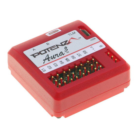
UNIT LAYOUT
Servo Ports
S1-S8
Servo Bus
Port B
Telemetry
Port
RECEIVER BINDING
Except in the case of DSM2/DSMX remote receiver connections, the receiver should be
bound prior to connecting to the Aura. Follow the instructions provided with your receiver.
For DSM2/DSMX remote receiver connections:
WARNING
1. A single remote receiver must always be connected to Mini Port 'A' . An additional
remote receiver (optional, of matching type) may be plugged into Mini Port 'B' .
2. Insert a bind plug(s) in Port S8 on the Aura for DSMX remote receiver(s) OR into Ports
S1 and S8 for DSM2 remote receivers.
3. Power the Aura with a 4.0VDC-10.0VDC power source. The LED on the remote
receiver(s) will begin to blink rapidly indicating that the receiver is in bind mode.
4. Put the transmitter in bind mode as described in the instructions. Binding is complete
when the receiver LED is solid. Remove and store bind plug(s) to complete the process.
DO NOT ATTEMPT RADIO SETUP WITH PROPELLER INSTALLED.
INADVERTENT POWER UP COULD CAUSE PERSONAL INJURY.
TRANSMITTER SETUP
The Aura 8 defaults to 3 ight modes that are changed via transmitter CH5/Gear which
should be assigned to a 3-position switch of your choice.
TRANSMITTER CONFIGURATION GUIDE
Aileron/Elevator/Rudder
ATV Setup
Throttle, CH5/Gear
Sub Trim
Veri ed neutral, TX sub trim not allowed
Trim Levers
Veri ed neutral
CH 5 (Gear)
Assigned to a 3-position switch
Reversing
All channels normal
FLIGHT MODES
Flight modes are an integral feature of the Aura 8. Each ight mode can be programmed
with a speci c set of dual rates, exponential, and control modes to suit a speci c type of
ying style or preference. Flight modes can be changed at any time during ight. Typically,
the ight mode switch is assigned to the CH5/Gear channel on a 3-position switch (a 2-
position switch may be used but the Aura will be limited to two (2) ight modes). A
common ight mode setup would be:
Flight Mode 1: Low Rates with Gyro O
Flight Mode 2: Low Rates With Low Gyro Gains
Flight Mode 3: High Rates with High Gyro Gains
Status Condition
CONTROL MODES
LEDs (4)
Control modes de ne how/if the Aura sensors a ect the servo outputs. Each control mode
has speci c settings such as gain, stick priority, gain scaling and each control mode can be
assigned one or more ight modes depending on the desired ying style or preference.
Micro USB Port
A common control mode setup would be:
Mini Port (A)
Control Mode A: Manual Control (Gyro O )
Control Mode B: Low Gyro Gains
Mini Port (B)
AURA 8 AIRFRAME INSTALLATION
Mount the Aura 8 to the airframe using the included double-sided foam tape. Please
observe the following rules for properly mounting your Aura. Any deviation from these
explicit conditions could cause improper function the device and may result in a crash.
1. Throughly clean the area to which the Aura will be mounted. Any surface dirt, dust,
grease, or oil will severely marginalize the foam tape's strength.
2. Ensure that the mounting surface is solid and not suceptible to ex or movement.
3. If installing in a high-performance airplane (larger than a typical park yer), place a
Velcro strap around the unit to prevent it from becoming dislodged during
high-energy maneuvering.
4. The Aura may be installed in any convenient location in the fuselage, noting:
§ The unit may be mounted upright or inverted as required in your installation.
§ The unit may be mounted in the longitudinal or lateral axis in any orthogonal
orientation. Use the Aura app to properly con gure the orientation.
For more in depth information, please visit:
www. exinnovations.com/aura
WARNING
NOTE
125%*
For best results with all other
non-JR brand transmitters,
100%*
ATV values are expected to
be between 90% and 140%
with 125% being ideal.
*JR XBus Mode B users
should set the throttle,
aileron, elevator, rudder, &
gear (CH5) values to 88%
Control Mode C: Medium Gyro Gains
Control Mode D: High Gyro Gains
Advertisement
Table of Contents

Related Manuals for potenza Aura 8


Summary of Contents for potenza Aura 8
- Page 1 For more in depth information, please visit: www. exinnovations.com/aura FPZAURA08 | User Guide The Aura 8 advanced ight control system is a giant leap forward in aircraft ight control WARNING system technology. Compatible with virtually every receiver on the market today via PWM connections, the Aura features special con gurations for DSM systems via remote receiver DO NOT ATTEMPT RADIO SETUP WITH PROPELLER INSTALLED.
- Page 2 CONNECTING A RECEIVER AURA 8 SOFTWARE CONFIGURATION- PC PROGRAM APP The Aura 8 supports three separate connection methods - direct connection of up to (2) For advanced users with complex airplanes, visit http://www. exinnovations.com/aura Declaration of Conformity (In accordance with ISO/IEC 17050-1) DSM2/DSMX remote receivers;...
Need help?
Do you have a question about the Aura 8 and is the answer not in the manual?
Questions and answers