Table of Contents
Advertisement
Quick Links
Advertisement
Table of Contents

Related Manuals for OZGENC MAKINA OMRM 127

Summary of Contents for OZGENC MAKINA OMRM 127
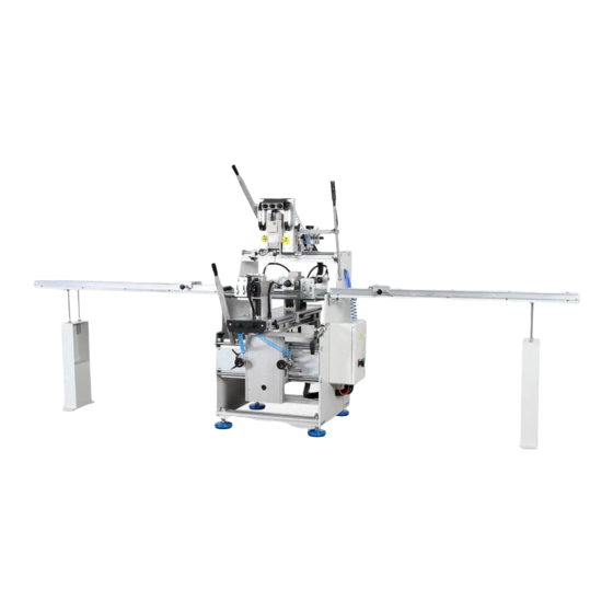
- Page 1 USER'S GUIDE 3 MOTORIZED ALUMINUM COPY ROUTER www.ozgencmakina.com.tr...
-
Page 2: Table Of Contents
1. DOCUMENT ISSUING INFORMATION Contents 1. DOCUMENT ISSUING INFORMATION ....................4 1.1 After-sales Service ......................... 4 1.2 Certification Process ........................5 1.3 Procedures to Follow ........................6 2. SCOPE OF USER'S GUIDE ........................7 3. Machine Description ........................... 8 Options: ............................8 3.1 Machine Cutting Capacity ...................... - Page 3 9.2 Turning on the Machine ......................30 9.3 Control List ..........................31 9.4 Moving Equipment on Machine ....................33 9.5 OMRM 127 3-Motor Aluminum Copy Router Machine and Machine Settings ......34 10. General Maintenance Issues ......................46 10.1 General Maintenance ........................ 46 10.2 Conditioner Water Level Control ....................
-
Page 4: Document Issuing Information
1. DOCUMENT ISSUING INFORMATION GENERAL INFORMATION Includes general topics related to the user's guide. 1. DOCUMENT ISSUING INFORMATION REVISION 2016 1.1 After-sales Service Address: Nilüfer Organize Sanayi Bölgesi 113. Sk. No:23 Nilüfer BURSA/TURKEY 16250 Contact: TEL: +90 224 411 07 46 FAX: +90 224 411 07 49 E-mail: info@ozgencmakina.com.tr Note: Spare parts are supplied by our below-mentioned company. -
Page 5: Certification Process
1. DOCUMENT ISSUING INFORMATION 1.2 Certification Process The machine (OMRM 127) with the technical features described in the user's guide is compatible with CE norms. Safety measures are taken in line with CE norms. CE documents are provided upon request. -
Page 6: Procedures To Follow
1. DOCUMENT ISSUING INFORMATION 1. DOCUMENT ISSUING INFORMATION 1.3 Procedures to Follow Warning symbols and phrases in this document should be taken into consideration. Warning symbols and phrases in this document should be taken into consideration. Warning symbols and phrases in this document should be taken into consideration. These warning signs are intended to protect These warning signs are intended to protect occupational health and avoid any hazard. -
Page 7: Scope Of User's Guide
2. SCOPE OF USER'S GUIDE 2. SCOPE OF USER'S GUIDE User’s guide is a document which must be read by the operating personnel before operating the machine. It covers all the required information for machine use. Information about how to provide long-term use of the machine and basic maintenance information is also contained in this document. -
Page 8: Machine Description
• Automatic cooling spray system • Full safety against occupational accidents • The power source protects the system from any sudden voltage change. Options: OMRM 127 3-motor aluminum copy router machine has no options. P a g e... -
Page 9: Machine Cutting Capacity
3. Machine Description 3.1 Machine Cutting Capacity OMRM 127 3-motor aluminum copy router machine can open door barrel slots, door handle holes and latch slots with the desired template. P a g e... -
Page 10: Machine Specifications
3. Machine Description 3.2 Machine Specifications 3.2 Machine Specifications Operating Voltage Voltage (V) Total Power Drawn Kilowatt (Kw) Current Drawn Ampere (A) Operating Pressure Total Air Consumption L/Min Motor Specifications Power Drawn 3 x 0,75 3 x 0,75 Kilowatt (Kw) Operating Frequency Hertz (Hz) Rotation Speed... - Page 11 Machine Weight Kilogram (Kg) 11 | P a g e...
-
Page 12: Machine Layout And Unit Structure
4. Machine Layout and Unit Structure 4. Machine Layout and Unit Structure General Machine Structure 12 | P a g e... - Page 13 4. Machine Layout and Unit Structure A- Vertical Cutter Operating Lever B- Vertical Cutter Follower Control Panel C- Vertical Cutter Motor D- Top Template E- Vertical Cutter Movement Lever F- Horizontal Cutter Motors G- Horizontal Cutter Operating Lever H- Horizontal Cutter Follower Control Panel İ- Template Followers J- Pressure/Fixing Supports K- Horizontal Template...
- Page 14 4. Machine Layout and Unit Structure Conveyor Structure A- Measurement Tape B- Profile Support C- Conveyor Feet 14 | P a g e...
-
Page 15: General Machine Size
4. Machine Layout and Unit Structure 4.1 General Machine Size 3740 mm 890 mm 15 | P a g e... - Page 16 4. Machine Layout and Unit Structure 1031 mm 1196 mm Machine Length: 3740 mm Machine Width: 1196 mm Machine Height: 1669 mm 16 | P a g e...
-
Page 17: Machine Placement
4.2. Machine Placement During machine installation, take the range of motion into account for Aluminum copy router cutting process. Also leave a suitable distance for machine panel doors for opening. Take following measures into account for safe operation. 500 mm 500 mm 17 | P a g e... -
Page 18: Occupational Safety And Measures
Operator is responsible for use, cleaning, adjustment, operation, maintenance etc. 5.3 Machine Usage and Misuse OMRM 127 3-motor Aluminum copy router machine is designed to open door barrel holes, door handle holes and latch slots. Any machine fault and occupational safety gap other than those resulting from procedures are under user’s responsibility. -
Page 19: Maintenance Measures For Safety
5. OCCUPATIONAL SAFETY and MEASURES alcohol or medication. Operator must check the machine and components prior to operation. It should be ensured that the main switch is turned off during routine maintenance. Power and pneumatics must also be switched off. Any pressure must be discharged in case any hydro- pneumatic equipment is used. -
Page 20: Connections
5. OCCUPATIONAL SAFETY and MEASURES 5.8 Connections All necessary connections must be prepared at the layout site in line with the machine. Electrical power, pneumatics or similar demands must be at values meeting requirements, and compatible equipment must be kept available at the layout site. Take IEC 64-8 norm into consideration for the installation of electrical equipment. -
Page 21: Safety Equipment
6. Safety Equipment DANGER! It is not permitted to remove or deactivate safety measures taken for the machine and equipment. A- Main Switch B- Cutter Operation Buttons 21 | P a g e... -
Page 22: Risky Areas And Warnings
/6. Safety Equipment 6.1 Risky Areas and Warnings 6.1 Risky Areas and Warnings Safety measures are taken on the machine through equipment, Safety measures are taken on the machine through equipment, but it is also required to comply but it is also required to comply with additional visual safety measures at the operating site. -
Page 23: Noise Emission
6.2 Noise Emission There is no noise emitted by machine units with an impact on occupational health. 6.3 Disposal of Hazardous Substances If the user uses lubrication and cooling equipment, then apply the methods indicated on respective labels. 23 | P a g e... -
Page 24: Machine Start-Up
7. Machine Start-up 7. Machine Start-up 7.1 Domestic Shipping Our machines are specially packed in accordance with the size and weight criteria. Main purpose of packaging is to safely deliver the product free-of-damage to our customer. Some parts may be shipped as disassembled in line with the agreements with customer. Prior to any shipment, a contract is signed between parties about all detailed criteria. -
Page 25: International Shipping
7. Machine Start-up A- Forklift B- Machine C- Shipment Vehicle Take necessary precautions during the machine is being taken off the vehicle. Take action to avoid any skid. You must lift the machine without damaging its body at unloading stage. Any machine foot dismounted during shipment must be reassembled. 7.2 International Shipping 25 | P a g e... -
Page 26: Fault Control During Shipment
7. Machine Start-up Any machine to be shipped abroad is packed in wooden boxes according to its size. Some environmental equipment with a risk of damage during packaging procedures must be demounted and separately packed. 7.3 Fault Control During Shipment Check the machine for any fault and damage that may arise during shipment and report to the shipping company in case you encounter a problem. -
Page 27: Machine Installation
8. Machine Installation 8. Machine Installation Expert M.S.K. personnel will carry out all procedures with regard to loading and unloading and conduct performance tests for assembly, mounting and start-up, if necessary. These procedures are evaluated on machine basis and carried out for products deemed necessary. Setting up of parts and equipment which should be prepared prior to machine use must be performed. - Page 28 8. Machine Installation A- Power Supply B- Driver C- 6A Fuse D- Relays E- 3-Contact Relay F- Electric Terminal Group 28 | P a g e...
-
Page 29: Pneumatic Connections
8. Machine Installation 8.6 Pneumatic Connections Ideal air pressure for the machine to properly function is 6 bar. Check the manometer. Attach the air hose from the compressor to this inlet. Caution: Make sure that your air supply is dry! Solenoid Valve group controls the motion of current pneumatic equipment. -
Page 30: Machine Use
9. Machine Use 9. Machine Use 9.1 Machine Start/Stop Make sure that there are no foreign objects on machine prior to operation. 9.2 Turning on the Machine Rotate the main switch clockwise until it slots into its place. 30 | P a g e... -
Page 31: Control List
9. Machine Use 9.3 Control List Main Switch: It completely cuts off the power supply from mains. A- Activates Left Follower on the Vertical Cutter B- Activates Press/Fixing Supports C- Activates Right Follower on the Vertical Cutter 31 | P a g e... - Page 32 9. Machine Use A- Activates Left Follower on the Horizontal Cutter B- Activates Right Follower on the Horizontal Cutter Contact with moving parts may lead to electric shock. Do not use sharp objects on protective isolation equipment as they may do harm. Do not use pointed objects that can penetrate into the protective isolation equipment.
-
Page 33: Moving Equipment On Machine
9. Machine Use 9.4 Moving Equipment on Machine A- Vertical Cutter Operating Lever B- Vertical Cutter Movement Tray C- Pressure/Fixing Supports D- Vertical Cutter Movement Lever E- Horizontal Cutter Operating Lever F- Horizontal Cutter movement Lever G- Horizontal Cutter Movement Tray 33 | P a g e... -
Page 34: Omrm 127 3-Motor Aluminum Copy Router Machine And Machine Settings
9. Machine Use 9.5 OMRM 127 3-Motor Aluminum Copy Router Machine and Machine Settings • Before working on OMRM 127 3-motor aluminum copy router, make sure the tray and all parts are clean and dry. • Remove all foreign objects and burrs on all surfaces of the machine. - Page 35 9. Machine Use • Adjust the length of the profile to be processed using the measuring reel available on the side of the conveyor and then fix the support. Measuring Support Reel 35 | P a g e...
- Page 36 9. Machine Use • After placing the profile rotate the Press/Fixing support button on the vertical cutter control panel to activate the supports. Press/Fixing Support Button Supports will be activated and the profile will be fixed. 36 | P a g e...
- Page 37 9. Machine Use Horizontal Cutter Operation Fixing Lever Measuring Reel • Loosen the fixing levers found on the sides of the follower to adjust the cutting depth checking the measuring reel available on the horizontal cutter group 37 | P a g e...
- Page 38 9. Machine Use • After placing the horizontal cutter follower on the template rotate the follower activation button on the horizontal cutter control panel Horizontal Cutter Left Follower Horizontal Cutter Left Activation Button Follower Activation Button 38 | P a g e...
- Page 39 9. Machine Use • Press and hold the horizontal cutter activation button ( Horizontal Cutter will be activated) While holding the horizontal cutter operation button pressed, push the horizontal • cutter movement lever forward to process on side of the profile and then pull back the movement lever to process the other side of the profile.
- Page 40 9. Machine Use Horizontal cutter movement lever 40 | P a g e...
- Page 41 9. Machine Use Vertical Cutter Operation • Before operating the vertical cutter fix the horizontal cutter tray Horizontal Cutter Tray Fixing Punch Vertical Cutter Follower Activation Button 41 | P a g e...
- Page 42 9. Machine Use • After placing the vertical cutter follower on the template, rotate the follower activation button on the horizontal cutter control panel Vertical Cutter Follower Template • Press and hold the vertical cutter activation button ( Vertical Cutter will be activated) 42 | P a g e...
- Page 43 9. Machine Use While holding the vertical cutter operation button pressed, pull the vertical cutter • movement lever downwards and complete the cutter operation. After completing the cutter operation, rotate the Press/Fixing support button on the • vertical cutter control panel to deactivate the supports and remove the profile. Repeat same actions for other profiles •...
- Page 44 9. Machine Use 9.6 Replacing Cutter Ends Fitting Screw Cutter Blade 1. Turn off main switch before replacing cutter blades 2. Remove the fitting screw using a switch 3. Pull and remove the milling cutter 4. Place the new blade 5.
- Page 45 9. Machine Use 9.7 Adjusting Follower Dimension • Ensure that the relevant control panel follower deactivation button of the follower for which dimension will be adjusted is closed. • Pull the follower from the top side towards yourself Follower top side •...
-
Page 46: General Maintenance Issues
10. General Maintenance Issues 10. General Maintenance Issues 10.1 General Maintenance REMARKS DAILY WEEKLY MONTHLY Cleaning top and surroundings of machine Cleaning of oil and other wastes Cleaning of moving parts Cleaning of slides and threaded rods Conditioner control (water, oil) Lubrication points Weekly maintenance Note:... -
Page 47: Conditioner Water Level Control
10. General Maintenance Issues 10.2 Conditioner Water Level Control There must be no water in the glass tube on the left side of conditioner (reservoir no. 1). Any accumulated water should be discharged. For this, press the plug under the tube upward or rotate it, depending on the type of the conditioner used for the machine. -
Page 48: Cylinder Settings
10. General Maintenance Issues 10.4 Cylinder Settings Loosen nut no. (1). Tighten or loosen bolt no. (2). This helps to adjust the pressure on the piston (6) within the cylinder (5) and to determine the speed of the cylinder to drive the engine. Loosening screw no. -
Page 49: Filter Maintenance
10. General Maintenance Issues Note: In normal standby position of the machine, backward and forward sensors of LED lights in relation to the cylinder position should be lit. You can adjust sensor settings using the special allen key located in the spare part box. 10.6 Filter Maintenance For pressure settings: Pull up the regulator cap "1". -
Page 50: Ergonomics
10. General Maintenance Issues 10.7 Ergonomics The machine is compliant with operating ergonomics. Operator's panel height and access to manually adjusted equipment are compliant. Electric and pneumatic panel access is viable. Ergonomic conditions for sampling, loading and pre-preparation are suitable. 50 | P a g e... -
Page 51: Problem Detection Chart
11. Problem Detection Chart 11. Problem Detection Chart FAILURE CAUSE SOLUTION Machine Fails to Draw • Main board switch Power Turned off • Turn on main switch Pneumatic Equipment Do • Machine fails to Not Operate draw air • Check the compressor line Pistons Do Not Mangle •... - Page 52 In case valve is broken • Valve coil may • Remount the coil have been • Tighten or replace dislocated cables • Coil cables may be • Oil the valve loose or burnt • Check hose • Valve may have •...
-
Page 53: Warranty Disclaimer
12. Warranty Disclaimer 12. Warranty Disclaimer The term of warranty starts as of the invoice date and it is 2 years. The machine is under our company's warranty for any manufacturing and material-related defects. If the machine breaks down within the term of warranty, the period of time spent to repair is added to the term of warranty. -
Page 54: Out Of Warranty Situations
12. Warranty Disclaimer 12.1 Out of Warranty Situations Consumables (milling, drilling bits, saws, teflon, etc.) are out of warranty. Damages to arise during shipment. Defects resulting from use of non-original parts. Defects resulting from user's lack of attention or knowledge. The machine must be initially started up by the service officer. -
Page 55: Annexes
13.Annexes 13.Annexes 13.1 ELECTRIC CIRCUIT DIAGRAM 13.2 PNEUMATIC DIAGRAM 13.3 EXPLODED PICTURES AND LIST OF MATERIALS 13.4 CE CERTIFICATE 13.5 LIST OF SPARE PARTS 55 | P a g e... - Page 56 13.Annexes 56 | P a g e...
- Page 57 13.Annexes 57 | P a g e...
- Page 58 13.Annexes WPSW A3 PP 4V210-08 24VDC 4V210-08 24VDC GFC-200-08 S3B-M5 S3HS S3B-M5 S3HS S3B-M5 S3HS S3B-M5 S3HS S3B-M5 S3HS 58 | P a g e...
- Page 59 13.Annexes 59 | P a g e...
- Page 60 13.Annexes 60 | P a g e...
- Page 61 13.Annexes 61 | P a g e...
- Page 62 13.Annexes 62 | P a g e...
- Page 63 13.Annexes 63 | P a g e...
- Page 64 13.Annexes 64 | P a g e...
- Page 65 13.Annexes 65 | P a g e...
- Page 66 13.Annexes 66 | P a g e...
- Page 67 13.Annexes 67 | P a g e...
- Page 68 13.Annexes 68 | P a g e...
- Page 69 13.Annexes 69 | P a g e...
- Page 70 13.Annexes 70 | P a g e...
- Page 71 13.Annexes 71 | P a g e...
- Page 72 13.Annexes 72 | P a g e...
- Page 73 13.Annexes 73 | P a g e...
- Page 74 13.Annexes 74 | P a g e...
- Page 75 13.Annexes 75 | P a g e...
Need help?
Do you have a question about the OMRM 127 and is the answer not in the manual?
Questions and answers