
Related Manuals for CAMBRIDGE CSW-10AT-CS

Summary of Contents for CAMBRIDGE CSW-10AT-CS
- Page 1 MODEL CSW-10AT-CS METER SET UP & OPERATION CAMBRIDGE SCALE WORKS, INC. PH: 800-292-7640 5011 HORSESHOE PIKE FX: 610-273-3612 PO BOX 670 HONEY BROOK, PA 19344 www.cambridgescale.com MANUAL P/N: 5999-1021-01 (8/11)
-
Page 2: Table Of Contents
TABLE OF CONTENTS Meter connections --------------------------------------------------------- 3 Operation ------------------------------------------------------------------- 4 & 5 1.0 Scale Procedure -------------------------------------------------------- 6 1.1 Software Navigation Flowchart --------------------------------- 6 & 7 1.2 Navigation Keys -------------------------------------------------- 7 1.3 Scale Menu Definitions ------------------------------------------ 8 &9 1.4 Numeric Entries -------------------------------------------------- 10 1.5 Set Up Parameters ------------------------------------------------ 10 2.0 Calibration Procedures ----------------------------------------------11 2.1 Calibration Menu Definitions -----------------------------------11... -
Page 3: Meter Connections
Meter Connections To connect power to the CSW-10AT-CS Meter. First make sure the On/Off Switch on the Rear of the meter is in the OFF position. Insert the battery in the battery holder, with the contacts pointing down, then slide down to lock into position. -
Page 4: Operation
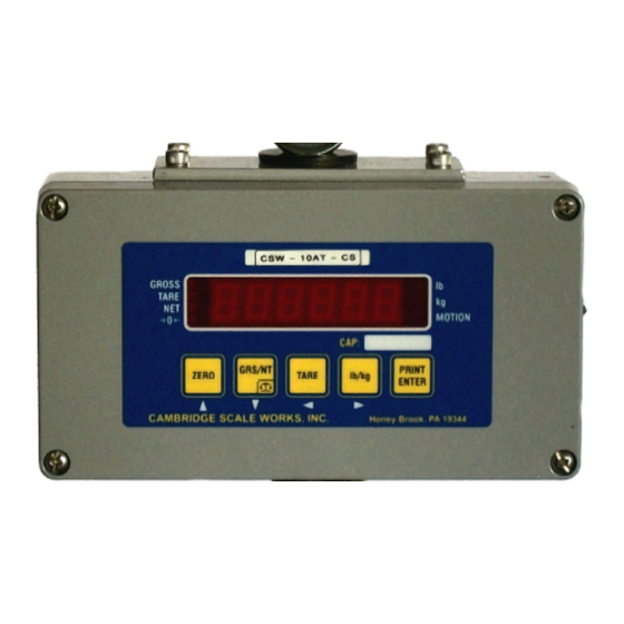
OPERATION Key Functions: ZERO Brings the scale to a zero balance reading. If the Zero key is pressed and held for 5 seconds the Calibration zero value will be displayed. GRS/NET Toggles the display between Gross weight and Net weight. This key is also used to enter setup mode. - Page 5 OPERATION CONTINUED Charging The Battery When the battery voltage falls to 6.5VDC, as described previously, bAt LO will be displayed continuously. The battery needs to be charged at this time. With the on/off switch in the OFF position, connect one end of the power adapter to a 110VAC outlet.
-
Page 6: Scale Procedure
1.0 SCALE PROCEDURE 1.1 SOFTWARE NAVIGATION FLOWCHART SCALE RS-232 CALIBRATION TEST Ntep,no,angle 1200,8,N,1- SOFTWARE SHOW RAW Zero & Clear All (Ntep) Ntep COUNTS THEN 0 BAUD RATE VERSION VERSION 19200,8,N,1? Points 1-999,999 WT ONLY, LIGHT SHOW RAW CAPACITY (5000) ZERO DISPLAY SEGMENTS COUNTS THEN 0... -
Page 7: Navigation Keys
1.1 SOFTWARE NAVIGATION FLOWCHART (CONTINUED) Normal, Blank, Motion Display Dashes (Normal) 1-99 ZERO BAND DIVISIONS(2) 0-99 ZERO DELAY UPDATES(2) 1-99 Zero Tracking DIVISIONS(1) 1-99 1/4secinc. Tracking DELAY lb ,kg, lb/kg Display lb/kg (lb/kg) 1-99 (1) 1.2 NAVIGATION KEYS SCALE ID ID IN TX During setup you will be required to make numeric entries. -
Page 8: Scale Menu Definitions
1.3 Scale Menu Definitions: NTEP (Ntep): Maximum divisions limited to 5000. scale negative message is displayed if the gross weight goes more than 10 divisions below zero. If a capacity and count by of more than 5000 divisions is selected ERR d will be displayed and you will be returned to S2 to select a new capacity or count by. - Page 9 1.3 Scale Menu Definitions Continued: S11 Zero Delay 0 to 99 updates (4) the weight display must be within the zero band for the selected number of updates to be considered Zero. S12 Zero Tracking 1 to 99 divisions (2) the number of graduations allowed to be Automatically Zeroed off.
-
Page 10: Numeric Entries
1.4 Numeric Entries When entering a numeric value, First press and release the lb/kg key to move right into the menu where the numeric value will be entered. Then press and release the Zero key, the first digit in the value will flash. Press and release the ZERO and GRS/NET keys to increase or decrease the digits value. -
Page 11: Calibration Procedures
2.0 CALIBRATION PROCEDURES 2.1 Calibration Menu Definitions: C1 Zero All Raw counts, (pitch and roll if in angle mode) will be displayed. When ZERO is pressed an analog Zero is done and all calibration span points will be cleared. If in angle mode the pitch and roll offsets will also be zeroed. C2 Zero Zeroed Raw counts, (pitch and roll if in angle mode will be displayed. -
Page 12: Calibration
2.2 Calibration Press and hold the GRS/NET key, as discribed Previously in section 1.4. ScAlE will be displayed. Press the lb/kg key to move right, CALib will be displayed. Press the GRS/NET key to move down, C1 will be displayed. Press the lb/kg key to move right, Raw counts will be displayed. -
Page 13: Communications Setup
3.0 COMMUNICATIONS SETUP 3.1 Communications Menu Definitions: R1 Baud Rate 1200 to 115200 baud (9600), 8, n, 1 R2 Output 0 - (Gross, Tare, Net)- "CR, LF, CR, LF [32 bytes of 2Eh], Format CR, LF, CR, LF, Gross (lb or kg), :, six ASCII characters [indicated weight], CR, LF, Tare (lb or kg), sp, :, six ASCII characters (indicated weight), CR, LF, CR, LF, CR LF, CR, LF"... - Page 14 3.0 COMMUNICATIONS SETUP 3.1 Communications Menu Definitions Continued: R4 Receiver 0 - Disabled - normal scale mode. 1 - Standard Receiver. Receives R3.3 RF link output string displaying data as it appears on the scale. All keys are disabled except the PRINT key.
-
Page 15: Testing Procedure
4.0 TESTING PROCEDURES 4.1 Testing Menu Definitions: T1 Version Displays Software Version. T2 Display Lights all display segments and indicating LED s T3 Buttons Press the Zero key, b1 will be displayed. Press the GRS/NET key, b2 will be displayed. Press the Tare key, b3 will be displayed. -
Page 16: Warnings
OSHA, MSHA, ANSI/ASME B30, Insurance, etc.. (Note: When using latches, If your hook or lifting eye becomes loose, remove the scale see instructions in“Understanding: The Crosby Group Warnings” for further from operation and contact CAMBRIDGE SCALE WORKS, information.) INC. immediately @ 1-301-724-4082 Always make sure the hook supports the load. -
Page 17: Warranty
CAMBRIDGE the equipment has not been mechanically, environmentally, or electrically abused. This warranty is limited, at the option of CAMBRIDGE, to repair, replace or an appropriate credit adjustment not to exceed the original equipment sale price paid to CAMBRIDGE. CAMBRIDGE assumes no liability in connection with the sales of its products beyond that stated above. -
Page 18: Assistance
7.0 Assistance If at any time you require assistance with you Model CSW-10AT-CS Meter please contact us at: CAMBRIDGE SCALE WORKS, INC. 11500 Bedford Road Cumberland, MD 21502 (301) 724-4082 Fax: (301) 724-4964 MANUAL P/N: 5999-1021-01 (8/11)
Need help?
Do you have a question about the CSW-10AT-CS and is the answer not in the manual?
Questions and answers