Table of Contents
Advertisement
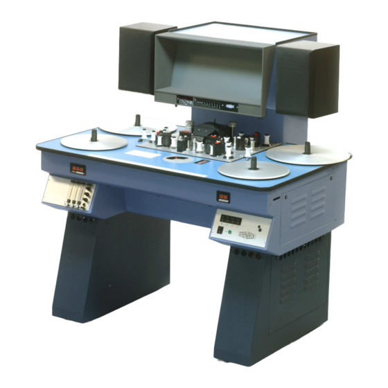
STEENBECK USER MANUAL 35mm 01-SERIES
Compact sized flatbed editors:
ST3511
2 plate, COMOPT sound.
ST1401
4 plate, COMOPT and 1 track SEPMAG sound.
ST401
4 plate, COMOPT and 1 track SEPMAG sound.
Larger sized flatbed editors:
ST701
6 plate, COMOPT and 2 tracks SEPMAG sound.
ST721
6 or 8, plate version with 2 picture system.
Copyright © 1978 – 2013.
Steenbeck is a trademark.
No part of this manual may be reproduced without the prior written permission of Steenbeck.
Specifications, colours etc. are subject to change without notice. Images are an example.
V01-2013
for 600 meters / 2000 feet of film.
for 600 meter / 2000 feet of film and perforated tape.
for 600 meter / 2000 feet of film and perforated tape.
picture-sound shift system for 1 track.
for 600 meter / 2000 feet of film and perforated tape.
picture-sound shift system for 2 tracks.
standard with one COMOPT and 2 tracks SEPMAG sound.
depending on version from 350 meter / 1200 feet up to
600 meter / 2000 feet of film and perforated tape.
picture-sound shift system for 2 tracks.
8 plate version can have 4 plates of 600 meter/2000 feet.
Advertisement
Table of Contents

Summary of Contents for Steenbeck 01 Series
- Page 1 8 plate version can have 4 plates of 600 meter/2000 feet. Copyright © 1978 – 2013. Steenbeck is a trademark. No part of this manual may be reproduced without the prior written permission of Steenbeck. Specifications, colours etc. are subject to change without notice. Images are an example. V01-2013...
-
Page 2: Table Of Contents
Table of contents user manual: Section page Table of contents Introduction General data Technical data : 3.1.1. introduction 3.1.2. film plates / film reels / cores 3.1.3 shrunken material 3.1.4 frictions picture sound general technical information Important safety and warranty information 4.1 safety 4.2 warranty fig. - Page 3 Connection loudspeakers and (optional) working lamp Maintenance instructions : 8.1 introduction replacing picture lamp replacing exciter/optical lamp adjustment pressure arms picture surface-coated mirrors polygon and lens screen illumination system frictions 21-22 8.10 general maintenance 8.11 adjustment guide ring 16mm List op slow and fast moving spare parts 35mm 01-Series 10.0 Operation field table top: 10.1 ST3511 10.2 ST401 ST1401 10.2 ST701...
-
Page 4: Introduction
This manual shows the way to use all the possibilities of this 35mm 01-Series film table. Caution: since the introduction of the 01 series many electronically / mechanically developments and improvements have been made. Be aware that the type number never have been changed since and therefor new and/or old parts/electronics not always been interchangeable. -
Page 5: Technical Data
3.1.1 Introduction: The Steenbeck 01-Series has a proven 1 motor drive technology. The table runs smoothly, because of the famous Steenbeck ‘speed switch’. This speed switch has fixed points for sync (synchronous 24 of 25 frames per second f.p.s.) forward and reverse, and adjustable notches between sync en maximum speed. -
Page 6: Picture
3.2 PICTURE. The rear screen projection method via an optical compensation system is done with 18-face revolving prism (polygon). With the high quality surface mirrors, optics and screen material gives this a very brilliant, bright and sharp image. The standard dimensions of the projection are 212 x 288 mm. Accurate film transport is achieved by revolving sprockets . -
Page 7: General Technical Information
6,3 Amp T and 0,5 Amps T The fuses can be found on the back side of the machine. (see fig. 4 page 10) Important: all fuses in the Steenbeck 01-Series are T (slow blown) and Should never be replaced by F (fast blown) fuses. -
Page 8: Important Safety And Warranty Information 4.1 Safety
If there is any mechanical or electronically alignment needed, these should be done by a Steenbeck engineer or by Steenbeck trained staff. It’s advised to use good trained staff to work with the Steenbeck machine. It’s very important that this personnel has read and studied the user manual. -
Page 9: Warranty
Defective parts should be send to the Steenbeck factory in Holland or the local agent/dealer at cost and risk of the owner/user of the Steenbeck machine. - Page 10 fig.1 V01-2013 35mm-01 serie...
- Page 11 17 18 fig. 2 25 26 fig.3 fig.4 V01-2013 35mm-01 serie...
- Page 12 fig 5 DRIVE DECK OVERVIEW (fig. 5) 34. polygon cover cap (support guide ring; not on photo) 51. switch for sound-shift system. ST401-701-721 only 35. pressure arm picture left and right 52. lens and prism system 36. pressure arm sound left and right 53.
-
Page 13: How To Use The 35Mm 01-Series
HOW TO USE THE STEENBECK 35mm 01 - SERIES: Read this section carefully, study all the possibilities and run some tests. Make the most important actions your own. 5.1 GENERAL OVERVIEW: (fig. 1 page 9) drive deck friction left friction right... -
Page 14: Drive Deck
HOW TO USE THE STEENBECK 35mm 01-SERIES. (continued) DRIVE DECK OVERVIEW ( 2 figures) (fig. 5 page 11) polygon cover cap (support guide ring; not on photo) pressure arm picture left and right pressure arm sound left and right COMOPT sprocket for film with sound... -
Page 15: Connecting To Mains Power
HOW TO USE THE STEENBECK 35mm 01-SERIES. (continued) 5.6 connecting to mains power: Connect the machine to the power network according to the instructions on page 5 with the supplied power cable. Make sure that this cable is well connected. -
Page 16: Rewind
It’s advised to rewind the film always with a (Steenbeck) film rewinder. The Steenbeck film rewinder can wind forward and backward and the speed can be adjusted, even to very slow. This can be useful when it’s required to check or clean the film by hand. -
Page 17: Universal Counter /Display
For ST3511 – ST(1)401 – ST701 – 2 counter ST721. The Steenbeck universal counter is designed to measure film length (all formats) and calculate the position and time information in common use. Additionally, the universal counter may offer extra possibilities for more effective work on your film rewind / film inspection table. -
Page 18: Picture - Sound Shift System (St401-St701-St721 Only)
UNIVERSAL COUNTER PICTURE – SOUND SHIFT SYSTEM. For ST401 – ST701 – ST721 The picture-sound synchronizer shows the shift of the sound tape against the picture tape in positive and negative directions. The range of display is ± 99.9 frames. The shift of the sound tape is accurate tot 1/100 of a frame –... -
Page 19: Connection Loudspeakers And (Optional) Working Lamp
ST701 7.0 Connecting loudspeakers and (optional) working lamp: All connections at the back of the frame. Work light: (fig. ) Connector for 230V light max. 60 Watt. The connection is as follows: 230 Volt: pin 1 = phase + / pin 2 = phase - / pin 3 = ground V01-2013 35mm-01 serie... -
Page 20: Maintenance Instructions
When the Steenbeck 01-Series is regularly in use (almost daily basis and more) the maintenance needs to be done at least once a year by the dealer or Steenbeck factory engineer. In this service the table will remain in a good condition. -
Page 21: Replacing Picture Lamp
When remounting the support be sure the surface of the base is clean, otherwise the upper film guide and sprocket ring do not line up. The objective and prism can only be cleaned with the housing removed. This should done by an Steenbeck engineer only because of optical alignment of the projected image. V01-2013... -
Page 22: Screen
The core plate of the friction should not be greased or lubricated at the bottom. The core axle fig.a should be greased a little bit. The film plate support fig.b (plastic ring friction plate / inner ring film plate fig.c) should have some Vaseline. (Steenbeck part number N000.0472.00) V01-2013 35mm-01 serie... -
Page 23: General Maintenance
core plate fig. a fig. b fig. c core axel friction disc plastic ring core friction axel inner ring film plate If metal film reels are used, the film plates and film core holders have to be taken off. The film reel is then placed upon the remaining square mandrel. This is only for 16mm film reels according ANSI PH 22.11 –... -
Page 24: Adjustment Guide Ring 16Mm
8.11 Adjustment guide ring 35mm. Old film, even new film can differ in width. The width “A” is normally set to 35mm – 0,2mm. If the film is bending on the film gate the width must be adjusted. The screw “B” ( hexagon 4mm) should be turned: a) gate larger: anticlockwise b) gate smaller: clockwise If the film is loose on the gate (horizontal picture jitter), the screw “B”... -
Page 25: List Op Slow And Fast Moving Spare Parts 35Mm 01-Series
9.0 LIST OF SLOW / FAST MOVING PARTS 35mm 01-Series. Fast moving parts: Part number 9956.0224.00 fuse 0,5A T (slow) 9956.0232.00 fuse 6,3A T 0056.0230.00 fuse 2,0A T 9956.0227.00 fuse 1,0A T 9956.1066.00 picture lamp, 12 V / 100W 9956.1080.00 sound exciter lamp Slow moving parts: Part number... -
Page 26: Operation Field Table Top: 10.1 St3511
10.0 OPERATION FIELD TABLE TOP. 10.1 SPEED SWITCH ST3511 fig.8 1. Speed selector (1) is activated by the speed control lever (2) in both directions. -first notch right; sync speed forward. -second notch right: winding speed forward, approx. 2/3 of maximum speed. -first notch left;... -
Page 27: St401 St1401
OPERATION FIELD TABLE TOP. 10.2 SPEED SWITCH ST(1)401 fig. 9 1. Speed selector (1) is activated by the speed control lever (2) in both directions. -first notch right; sync speed forward. -second notch right: winding speed forward, approx. 2/3 of maximum speed. -first notch left;... -
Page 28: St701
OPERATION FIELD TABLE TOP. 10.3 SPEED SWITCH ST701 fig.10 1. Speed selector (1) is activated by the speed control lever (2) in both directions. -first notch right; sync speed forward. -second notch right: winding speed forward, approx. 2/3 of maximum speed. -first notch left;... -
Page 29: St721
10.0 OPERATION FIELD TABLE TOP. 10.4 SPEED SWITCH ST721 fig.11 1. Speed selector (1) is activated by the speed control lever (2) in both directions. -first notch right; sync speed forward. -second notch right: winding speed forward, approx. 2/3 of maximum speed. -first notch left;... -
Page 30: Adjustment Picture Lamp 35Mm (All Models)
For uniform illumination to the left and right of the screen. Picture lamp adjustment should be carried out with machine in operation in sync speed, but without film. It is advisable to start with the screws 3 and 5. Use Hexagon 4mm Steenbeck part number V01-2013 35mm-01 serie... -
Page 31: St3511 Picture Only
ST3511 picture only ST3511 picture with optical sound COMOPT V01-2013 35mm-01 serie... -
Page 32: St401 / 1401 Picture W/O Sound / W Mag Sound
ST1401 picture w/o sound with SEPMAG ST1401 picture with optical sound COMOPT V01-2013 35mm-01 serie... -
Page 33: Picture W Commag
ST1401 picture with COMMAG sound COMMAG only with special replay head, 2 and 4 track ST701 picture with optical sound COMOPT V01-2013 35mm-01 serie... -
Page 34: St701 Picture With Comopt Sound
ST701 picture w/o sound, SEPMAG sound ST721 L picture w/o sound R picture with optical sound V01-2013 35mm-01 serie... -
Page 35: St721 Picture With Comopt Sound
ST721 pictures w/o sound / SEPMAG sound V01-2013 35mm-01 serie... -
Page 36: Pictures St701 And St721
ST701 ST721 with optional video STEENBECK B.V. (Ltd.) Keizersveld 31, 5803 AM VENRAY. The Netherlands Tel: +31 (0)478 63 03 00 Fax: +31 (0)478 69 00 07 info@steenbeck.com www.steenbeck.com V01-2013 35mm-01 serie...
Need help?
Do you have a question about the 01 Series and is the answer not in the manual?
Questions and answers