Table of Contents
Advertisement
Quick Links
D3000M SERIES USERS MANUAL
REVISED: 9/15/08
DGH CORPORATION
P. O. BOX 5638
MANCHESTER, NH 03108
TELEPHONE: 603-622-0452
FAX: 603-622-0487
URL: www.dghcorp.com
The information in this publication has been carefully checked and is
believed to be accurate; however, no responsibility is assumed for possible
inaccuracies or omissions. Applications information in this manual is in-
tended as suggestions for possible use of the products and not as explicit
performance in a specific application. Specifications are subject to change
without notice.
D3000M modules are not intrinsically safe devices and should not be used
in an explosive environment unless enclosed in approved explosion-proof
housings.
Advertisement
Table of Contents

Related Manuals for DGH D3000M Series

Summary of Contents for DGH D3000M Series
- Page 1 D3000M SERIES USERS MANUAL REVISED: 9/15/08 DGH CORPORATION P. O. BOX 5638 MANCHESTER, NH 03108 TELEPHONE: 603-622-0452 FAX: 603-622-0487 URL: www.dghcorp.com The information in this publication has been carefully checked and is believed to be accurate; however, no responsibility is assumed for possible inaccuracies or omissions.
-
Page 2: Table Of Contents
TABLE OF CONTENTS Warranty CHAPTER 1 Getting Started Quick Hook-Up Module Configuration 1-5 Modbus Protocol 1-7 Modbus Exceptions (Errors) 1-12 Modbus Register Map 1-14 Modbus Enable/Disable 1-15 CHAPTER 2 Functional Description Block Diagram CHAPTER 3 Communications Data Format RS-232C Multi-party Connection 3-3 Changing Baud Rate RS-485 RS-485 Multidrop System... -
Page 3: Warranty
WARRANTY DGH warrants each D3000M series module to be free from defects in materials and workmanship under normal conditions of use and service and will replace any component found to be defective, on its return to DGH, transportation charges prepaid within one year of its original purchase. DGH assumes no liability, expressed or implied, beyond its obligation to replace any component involved. -
Page 4: Chapter 1 Getting Started
Configuration of each module can be performed using either the DGH Utility Software (shipped on CD-ROM with each order) or use Windows Hyper-terminal to manually configure a module. The DGH Utility Software CD-ROM can be downloaded from our website www.dghcorp.com. - Page 5 2. Click on the “My Computer” icon on your Windows Desktop, a window will open that lists all the computer drives. 3. Click on the drive icon that says “Dgh”. A new window will open. 4. Click on the file “setup.exe” and run this program.
- Page 6 Getting Started 1-3 Figure 1.1b Connection to DB-25 host computer serial port. Notes: 1. The module DEFAULT* pin is connected to GND in each of these illustrations. Whenever, DEFAULT* is grounded, the module will only communicate at 300 baud. The parity setting should be No parity, eight data bits and one stop bit.
- Page 7 Getting Started 1-4 The following connection diagrams illustrate how to connect a RS- 485 module to a host computer. Figure 1.2 illustration shows how to connect an RS-485 module to a host PC serial port. This illustration should be used only for configuration of modules. It is not recom- mended, or suitable for installed applications.
- Page 8 Getting Started 1-5 The polarity of the DGH RS-485 lines is indicated above. It should be noted that ‘(Y) Data’ is the Positive (+) line. The ‘(G) Data*’ line is the Minus (-) line. Note: The module DEFAULT* pin is connected to GND in each of these illustrations.
- Page 9 Getting Started 1-6 11. Select the four-digit model number from the “Model” drop-down list box. 12. Press the ‘Read Setup’ button. 13. A progress bar will appear while the program is reading the mod- ule parameters. If no communications errors are displayed then the module is communicating properly with the host computer.
- Page 10 D3000M Modbus RTU Protocol The D3000M series modules support several of the Modbus RTU protocol functions. These functions read and write values to register locations within the D3000M. The values and register locations con- trol features such as the Analog Output value, the Slope control value, and the Watchdog Timer value.
- Page 11 Modbus function (01) Read Coil Status will read the status of dis- crete digital inputs. Modbus relay input coils are considered the digi- tal input bits on the D3000M series modules. This function can be used to read status of the digital input bits. The D3000M digital input bits DI0 to DI2 correspond to Modbus coils 0x00001 to 0x00003.
- Page 12 Modbus function (02) Read Input Status will read the status of the D3000M digital inputs. Modbus inputs are the digital inputs on the D3000M series modules. This function can be used to read the sta- tus of digital input bits DI0, DI1 and DI2. These bits correspond to Modbus coils 0x10001 to 0x10003.
- Page 13 Getting Started 1-10 A typical command and response to read the analog output value from a D3000M whose slave address is ‘01’ would be: Command: 03 03 00 00 00 01 85 E8 Response: 03 03 02 00 7D 01 A5 In the command string: is the slave address is the Read Input Registers command...
- Page 14 This command can also be used to suspend the Modbus RTU proto- col mode and return the D3000M back to the DGH ASCII protocol mode. Write a value of 0000 to Modbus register 40003 to temporarily suspend the Modbus RTU protocol mode. The module will then com- municate using the D3000M ASCII protocol command set.
- Page 15 Modbus Slave device when a problem or error is detected. These error values are referred to as “exception codes” and the DGH implementation of the Modbus RTU protocol utilizes these exception codes when applicable. See Table 3.0 below for a complete list of supported exception codes.
- Page 16 0x83. A typical exception response would be: Command: 03 03 00 0A 00 01 A5 EA Response: 03 83 02 61 31 The following error codes may be returned from a DGH D3000M Modbus RTU compatible module. Table 3.0. DGH Modbus Exception Codes. Exception Name Description...
- Page 17 Digital Input 1 00003 Read Digital Input 2 40001 Write 0.FFFF Analog Output Value 40003 Write Temporarily suspend Modbus RTU and return back to DGH ASCII protocol. 40003 Write Reset Module 40004 Write 0.FFF RAW DAC Output 40005 Write 10.FFFF EEPROM Slope...
-
Page 18: Modbus Protocol
Modbus Disable (MBD) The Modbus Disable (MBD) command is used to disable the Modbus RTU protocol. Any D3000M series module in Modbus mode can be returned to D3000 ASCII protocol mode by connecting a jumper wire between module pins GND and Default* pin. This places the mod- ule in Default Mode, where the module will only communicate at 300 baud, no parity, D3000 ASCII protocol, and answer to any address. - Page 19 Getting Started 1-16 Response: *1MBD2E Testing and Troubleshooting: 1. The RS-485 type D3000M modules “cannot” be tested in the Modbus RTU protocol mode using the DB-9 connection in Figure 2.0. The RS-485 Quick Hook-up Diagram to an RS- 232 serial port causes the command to be read back into the computer before the response from the module.
-
Page 20: Chapter 2 Functional Description
Chapter 2 Functional Description The D3000M Computer to Analog Output interfaces provide accurate analog process control signals in response to simple digital commands from a host computer. The D3000M units are completely self-contained and are designed to be operated remotely from the host. Digital commands are transmitted to the D3000M units using standard RS-232 or RS-485 commu- nications links. - Page 21 Functional Description 2-2 The last major block in the diagram is the power supply. The power supply converts the raw 10 to 30 volts supplied by the user into regulated voltages used in the module. It produces +5V necessary to operate the microproces- sor and EEPROM.
- Page 22 Functional Description 2-3...
-
Page 23: Chapter 3 Communications
Chapter 3 Communications Introduction The D3000M modules have been carefully designed to be easy to interface to all popular computers and terminals. All communications to and from the modules are performed in Modbus RTU format. This system allows multiple modules to be connected to a communications port with a single 4-wire cable. -
Page 24: Data Format
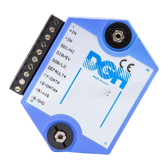
Communications 3-2 Data Format All modules communicate in standard NRZ asynchronous data for- mat. This format provides one start bit, seven data bits, one parity bit and one stop bit for each character. RS-232C RS-232C is the most widely used communications standard for information transfer between computing equipment. - Page 25 Communications 3-3 each module are labelled with notations (B), (R), (G), and (Y). This designates the colors used on standard 4-wire telephone cable: Label Color (B) GND Black (R) V+ (G) DATA* Green (Y) DATA Yellow This color convention is used to simplify installation. If standard 4-wire telephone cable is used, it is only necessary to match the labeled pins with the wire color to guarantee correct installation.
- Page 26 Communications 3-4...
-
Page 27: Chapter 4 Command Set
Chapter 4 Command Set The D3000M modules operate with a simple command/response protocol to control all module functions. A command must be transmitted to the module by the host computer or terminal before the module will respond with useful data. A module can never initiate a communications sequence. A variety of commands exists to exploit the full functionality of the modules. - Page 28 The most common type of data used in commands and responses is analog data. Analog data is always represented in the same format for all models in the D3000M series. Analog data is represented as a nine-character string consisting of a sign, five digits, decimal point, and two additional digits. The string represents a decimal value in engineering units.
- Page 29 Command Set 4-3 appears when large data values saved in the module’s EEPROM are read back. In most practical applications, the problem is non-existent. The Digital Input, Hex Output and Setup commands use hexadecimal representations of data. The data structures for these commands are detailed in the command descriptions.
- Page 30 Command Set 4-4 1) a normal response indicated by a ‘ * ‘ prompt 2) an error message indicated by a ‘ ? ‘ prompt 3) a communications time-out error When a module receives a valid command, it must interpret the command, perform the desired function, and the communicate the response back to the host.
-
Page 31: User Commands
Command Set 4-5 Response Checksums If the long form ‘#‘ version of a command is transmitted to a module, a checksum will be appended to the end of the response. For example: Command: $1RD (short form) Response: *+00072.10 Command: #1RD (long form) Response: *1RD+00072.10A4... - Page 32 Command Set 4-6 Table 4.1 D3000 Command Set Command Definition Typical Typical Command Response Message Message D3000M Commands Acknowledge $1ACK Analog Output $1AO+00020.00 Digital Input $1DI *0007 Hex Output $1HX0FFF Read Analog Output $1RAO *+00017.50 Read Data $1RD *+00012.34 Read High Limit $1RHI *+00020.00 Read Identification...
- Page 33 Command Set 4-7 Acknowledge (ACK) The ACKnowledge command is a hand-shaking command used in conjunc- tion with the Analog Output (AO) command. It is used to confirm the data sent to a module. See the Analog Output (AO) command for examples of ACK usage.
- Page 34 Command Set 4-8 This time the host verifies that the data is correct and commands the module to complete the task: Command: $1ACK Response: Only at this point will a change occur on the analog output. The output data specified in the AO command must lie within the input range of the module or else the command is aborted and the module will respond with a LIMIT ERROR message.
- Page 35 Command Set 4-9 The DI command will return the state of the digital inputs even if one of the Manual Modes is in effect. When reading digital inputs with a checksum, be sure not to confuse the checksum with the data. Hex Output (HX) The HeX Output (HX) command controls the analog output by sending hexadecimal data directly to the Digital to Analog Converter (DAC).
- Page 36 Command Set 4-10 IDentification (ID) The IDentification (ID) command allows the user to write a message into the nonvolatile memory which may be read back at a later time with the Read IDentification (RID) command. It serves only as a convenience to the user and has no other affect on module operation.
- Page 37 Modbus Disable (MBD) The Modbus Disable (MBD) command is used to disable the Modbus protocol. A D3000M series unit in Modbus mode can be returned to ASCII protocol mode by connecting a jumper wire between pins GND and Default* pin. This places the module in Default Mode, where the module will only communicate at 300 baud, no parity, DGH ASCII protocol, and answer to any address.
- Page 38 Command Set 4-12 the eventual final output of the analog output. The RAO simply reads back the argument of the most recent AO command and does not necessarily correlate with the actual analog output. See the RD command. Command: $1RAO Response: *+00017.50 Command:...
- Page 39 Command Set 4-13 Command: $1RID Response: *BOILER ROOM (example) Command: #1RID Response: *1RIDBOILER ROOM54 (example) In this case the RID command has read back the message “BOILER ROOM” previously stored by the ID command. See ID command. Read LOw Limit (RLO) The Read LOw limit (RLO) command reads back the LO limit data stored in the nonvolatile memory.
- Page 40 Command Set 4-14 The response contains two bytes. The second byte contains the Modbus slave address, in this example 01. The first byte indicates whether the Modbus protocol is enabled or not enabled. In this example 00 indicates that the Modbus protocol is not enabled. If the first byte were 01 the Modbus protocol is enabled.
- Page 41 Command Set 4-15 Remote Reset (RR) The Remote Reset (RR) command allows the host to perform a program reset on the module’s microcomputer. This may be necessary if the module’s internal program is disrupted by static or other electrical distur- bances.
-
Page 42: Ascii Error Messages
Command Set 4-16 in minutes: Command: $1WT+00010.00 Response: Command: #1WT+00010.00 Response: *1WT+00010.00B0 These two command examples set the watchdog time value to 10 minutes. In this example, if the module does not receive a valid command for a period of 10 minutes, the analog output will automatically be forced to the Starting Value. - Page 43 Command Set 4-17 All modules feature extensive error checking on input commands to avoid erroneous operation. Any errors detected will result in an error message and the command will be aborted. All error messages begin with “?”, followed by the channel address, a space and error description.
- Page 44 Chapter 5 Setup Information/SetUp Command All Modbus modules are setup before installation using the SetUp (SU). The user options include a choice of baud rate, parity, address, and many other parameters. The particular choice of options for a module is referred to as the setup information.
-
Page 45: Command Syntax
Setup Information and SetUp Command 5-2 Command Syntax The general format for the SetUp (SU) command is: $1SU[byte1][byte 2][byte 3][byte 4] A typical SetUp command would look like: $1SU31070180. Notice that each byte is represented by its two-character ASCII equivalent. In this example, byte 1 is described by the ASCII characters ‘31’... - Page 46 Setup Information and SetUp Command 5-3 When using the SU command to change the address of a module, be sure to record the new address in a place that is easily retrievable. The only way to communicate with a module with an unknown address is with the Default Mode.
- Page 47 Setup Information and SetUp Command 5-4 Byte 2 Byte 2 is used to configure some of the characteristics of the communica- tions channel; linefeeds, parity, and baud rate. Linefeeds The most significant bit of byte 2 (bit 7) controls linefeed generation by the module.
- Page 48 Setup Information and SetUp Command 5-5 accidently lost. This is very important when changing the baud rate of an RS- 232C string. Let’s run through an example of changing the baud rate. Assume our sample module contains the setup data value of ‘31070180’. Byte 2 is ‘07’. By referring to the SU command chart we can determine that the module is set for no linefeeds, no parity, and baud rate 300.
- Page 49 Setup Information and SetUp Command 5-6 If the module does not respond to the new baud rate, most likely the setup data is incorrect. Try various baud rates from the host until the module responds. The last resort is to set the module to Default Mode where the baud rate is always 300.
- Page 50 Setup Information and SetUp Command 5-7 In some systems, such as IBM BASIC, a carriage return (CR) is always followed by a linefeed (LF). The modules will respond immediately after a command terminated by a CR and will ignore the linefeed. To avoid a communications collision between the linefeed and the module response, the module should be setup to delay by 2 units.
-
Page 51: Setup Hints
Setup Information and SetUp Command 5-8 Table 5.4 Byte 4 Displayed Digits and Manual Mode Select BYTE 4 FUNCTION DATA BIT +XXXX0.00 DISPLAYED DIGITS +XXXXX.00 DISPLAYED DIGITS +XXXXX.X0 DISPLAYED DIGITS +XXXXX.XX DISPLAYED DIGITS 1 NOT USED MANUAL MODES ENABLED MANUAL MODES DISABLED UP/DOWN MODE CONTROLLER INPUT LIMIT SWITCHES N. - Page 52 Setup Information and SetUp Command 5-9 Table 5.5 Factory Setups by Model. (All modules from the factory are set for address ‘1’, 300 baud, no parity) Model Setup Message D312XM, D316XM 31070180 D313XM, D314XM, D317XM, D318XM 31070140 D325XM, D326XM 310701C0 Setup Software Windows utility software for the PC and compatibles is available to facilitate module setup.
-
Page 53: Chapter 6 Digital I/O Function
Chapter 6 Digital I/O Functions and Manual Mode MANUAL MODES/DIGITAL INPUTS Each D3000M module has three digital input connections designated as DI0/DN*, DI1 /UP*, and DI2. These inputs have a dual function; they may be used as control inputs which influence the analog output or they may be used as general-purpose digital inputs. - Page 54 Digital I/O Functions and Manual Mode 6-2 MANUAL MODES The D3000M modules may be configured to use the digital inputs to control the analog output. These functions are called Manual Modes. Four different Manual Modes may be specified: Up/Down Controller Input Limit Switch NO Limit Switch NC These modes are selected by Bits 0 and 1 of Byte 4 in the Setup data.
- Page 55 Digital I/O Functions and Manual Mode 6-3 Figure 6.2 Manual Up/Down Control. The slope rate on D3000M modules is fixed and cannot be changed. The manual slope on D3000M units is scaled so that a full-scale output change requires 5 seconds to complete. The Manual Modes have priority over host-generated output commands.
-
Page 56: Controller Input
Digital I/O Functions and Manual Mode 6-4 Figure 6.3 Manual Up/Down Control With Host Lock-Out. CONTROLLER INPUT This Manual Mode is a variation of the manual up/down control specifically setup for operation with ON-OFF controllers. With this mode, a D3000M unit may be used to add an analog control output to an ON-OFF or time- proportional controller. -
Page 57: Limit Switches
Digital I/O Functions and Manual Mode 6-5 LIMIT SWITCHES Two of the Manual Modes allow the use of limit switches or other external digital signals to limit the analog output that may be obtained with the Analog Output (AO) command. The limit switch mode may be programmed to accommodate either normally-open (NO) switches or normally-closed (NC) switches. - Page 58 Digital I/O Functions and Manual Mode 6-6 Figure 6.5 Using Limit Switches To Stop An Analog Output Ramp. On D3000M units with controlled output ramps, the limit switches will stop the output even after a successful AO command. Figure 6.5 illustrates this action.
-
Page 59: Chapter 7 Power Supply
Small systems may be powered by using wall-mounted calculator-type modular power supplies. These units are inexpensive and may be obtained from DGH (PS-3) or many retail electronics outlets. For best reliability, modules operated on long communications lines (>500 feet) should be powered locally using small calculator-type power units. This eliminates the voltage drops on the Ground lead which may interfere with communications signals. -
Page 60: Chapter 8 Troubleshooting
Chapter 8 Troubleshooting Symptom: RS-232 Module is not responding to commands. RS-485 Module is not responding to commands. Module responds with ?1 COMMAND ERROR TO every command. Characters in each response message appear as graphics characters. • RS-232 Module is not responding to commands 1. - Page 61 • RS-485 Module is not responding to commands 1. Perform steps 1, 2, 4, 5 and 6 listed above. 2. Ensure that module RS-485 "Data" line (module terminal pin #7) is connected to the Host RS-485 "Data+" line. 3. Ensure that module RS-485 "Data*" line (module terminal pin #8) is connected to the Host RS-485 "Data-"...
-
Page 62: Chapter 9 Calibration
Chapter 9 Calibration D3000M units feature state-of-the art digital trimming techniques to elimi- nate the need for calibration pots or other hardware trims. Calibration is performed with trim commands through the communications port. The on- board microprocessor is used to calculate calibration constants which are then stored in the nonvolatile EEPROM. - Page 63 Calibration 9-2 Calibration Procedure-Voltage units 1) Connect voltmeter to analog output 2) Set the output to -full scale with Analog Output (AO) command. 3) Measure the output voltage. 4) Report the actual output value to the module with the Trim MiNimum (TMN) command.
- Page 64 Calibration 9-3 The measured output is +10.123V. Report the measured output to the module with the Trim Maximum (TMX) command: Command: $1WE Response: Command: $1TMX+10123.00 Response: The output now measures +10.005V, which is still not within specification. Repeat the TMX command with the new value: Command: $1WE Response:...
-
Page 65: Appendix Aascii Table
Appendix A ASCII TABLE Table of ASCII characters (A) and their equivalent values in Decimal (D), Hexadecimal (Hex), and Binary. Claret (^) represents Control function. Hex Binary Hex Binary ^@ 0 00000000 10000000 00000001 10000001 00000010 10000010 00000011 10000011 00000100 10000100 00000101 10000101... - Page 66 ASCII TABLE A-2 Hex Binary Hex Binary 00100011 10100011 00100100 10100100 00100101 10100101 & 00100110 10100110 ‘ 00100111 10100111 00101000 10101000 00101001 10101001 00101010 10101010 00101011 10101011 00101100 10101100 00101101 10101101 00101110 10101110 00101111 10101111 00110000 10110000 00110001 10110001 00110010 10110010 00110011 10110011...
- Page 67 ASCII TABLE A-3 Hex Binary Hex Binary 01001100 11001100 01001101 11001101 01001110 11001110 01001111 11001111 01010000 11010000 01010001 11010001 01010010 11010010 01010011 11010011 01010100 11010100 01010101 11010101 01010110 11010110 01010111 11010111 01011000 11011000 01011001 11011001 01011010 11011010 01011011 11011011 01011100 11011100 01011101 11011101...
- Page 68 ASCII TABLE A-4 Hex Binary Hex Binary 01110101 11110101 01110110 11110110 01110111 11110111 01111000 11111000 01111001 11111001 01111010 11111010 01111011 11111011 01111100 11111100 01111101 11111101 01111110 11111110 01111111 11111111...
- Page 69 Appendix B D3000M Specifications Specifications (@ +25°C and nominal power supply voltage). Analog Output • Single channel analog output. Voltage: 0-1V, ±1V, 0-5V, ±5V, 0-10V, ±10V. Current: 0-20mA, 4-20mA. • Output isolation to 500V rms. • 12-bit output resolution. • Accuracy (Integral & Differential Nonlinearity): 0.1%FSR (max). •...
- Page 70 D3000M Specifications B-2 Power Requirements: Unregulated +10V to +30Vdc, 0.75W max (Voltage Output), 1.0W max (Current Output). Internal switching regulator. Protected against power supply reversals. Environmental Temperature Range: Operating -25°C to +70°C. Storage -25°C to +85°C. Relative Humidity: 0 to 95% noncondensing. Mechanical &...
Need help?
Do you have a question about the D3000M Series and is the answer not in the manual?
Questions and answers