Advertisement
• Complete control of R-BUS(x) back plane
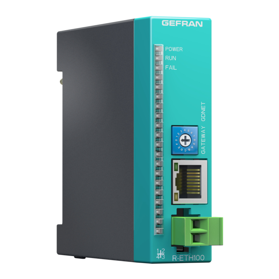
• Ethernet interface, Modbus protocol over TCP
• Power supply of backplane
This section contains the instructions necessary for correct
installation of the GIloGIK II into the machine control panel
or the host system and for correct connection of the system
power supply, inputs, outputs and interfaces.
Before proceeding with installation read the following
warnings carefully!
Remember that lack of observation of these warnings
could lead to problems of electrical safety and electroma-
gnetic compatibility, as well as invalidating the warranty.
Qualified staff
the installation and use of the system and components are only reserved
at qualified staff.
Conform use
the system and relative components are usable exclusively to the use
previewed in the manual
In order to guarantee a correct and sure operation are indispensable that
the product comes transported, stored correctly, installed, and controlled
second the previewed modalities.
Suitable for use in pollution degree 2 environment.
Open type equipment
Electrical power supply
• the GILOGIK II is NOT equipped with an On/Off switch: the user must
provide a two-phase disconnecting switch that conforms to the required
safety standards (CE marking), to cut off the power supply upstream of
the system. The switch must be located in the vicinity of the system and
must be within easy reach of the operator.
One switch may control more than one systems.
• To make sure that the system very is connected to earth second the
detailed lists of the relative understood one it.
• if the system is used in applications with risk of damage to persons,
machinery or materials, it is essential to connect it up to auxiliary
security equipment. It is advisable to make sure that alarm signals are
also triggered during normal operation.
The dispositif must NOT be installed in flammable or explosive
environments; it may be connected to equipment operating in such
atmospheres only by means of appropriate and adequate types of
interface, conforming to the applicable safety standards
Notes Concerning Electrical Safety and Electromagnetic
80126C_MHW_R-ETM100_08-2011_ENG
R-ETM100
GATEWAY Modul ModBuS oVER TCP
INSTALLATION AND OPERATION MANUAL
cod. 80126C Edit 04 - 08/2011 - ENG
1 • MAIN FEATURES
I
2 • INSTALLATION AND CONNECTION
Compatibility:
• CE MARKING: EMC Conformity (electromagnetic compatibility)
in accordance with EEC Directive 2004/108/CE. The GILOGIK II
system is mainly designed to operate in industrial environments,
installed on the switchboards or control panels of productive process
machines or plants.
Norm of applicable product EN 61131-2.
The Declaration of conformity is available on GEFRAN web:
www.gefran.com
• UL listed standard: UL508 file E198546
• BT Conformity (low tension)
in accordance with Directive LVD 2006/95/CE.
Advice for Correct Installation for EMC
Module power supply
• Supply with class 2 device
• The power supply to the modules on the switchboards must always
come directly from an isolation device with a fuse.
• The electronic instruments and electromechanical power devices such
as relays, contactors, solenoid valves, etc., must always be powered
by
separate lines.
• When the power supply is strongly disturbed by the commutation of
transistor or power units or motors, an isolation transformer should be
used, earthing the screen.
• It is essential that the plant has a good earth connection:
- the voltage between neutral and earth must not be > 1V
- the Ohmic resistance must be < 6Ω;
• In the proximity of high frequency generators or arc welders, use
adequate filters.
• The power supply lines must be separate from the instrument input
and output ones.
GEFRAN S.p.A. declines all responsibility for any damage
to persons or property caused by tampering, neglect,
improper use or any use which does not conform to the
characteristics of the controller and to the indications
given in these Instructions for Use.
3
Advertisement
Table of Contents

Related Manuals for gefran R-ETM100

Summary of Contents for gefran R-ETM100
- Page 1 It is advisable to make sure that alarm signals are GEFRAN S.p.A. declines all responsibility for any damage also triggered during normal operation. to persons or property caused by tampering, neglect,...
- Page 2 Working Temperature: 0...50°C - power supply on (yellow POWER led) Storage Temperature: -20...70°C - module in run / configuration (green RUN led) Humidity: max. 90% Rh not condensing - module or system in alarm / not configurated (red FAIL led) For UL: Maximum surrounding air temperature 50°C 4 • CONNECTIONS (*) Use standard category 6 cable according to TIA/EIA-568A (**) Use unipolar cable with 1-1.5mm cross section Do not attach a lug Yellow LED POWER Green LED RUN Red LED FAIL Configurator of the net MODBUS over TCP Green LED DATA Ethernet (*) RJ45 Yellow LED LINK Supply (**) 24Vdc ± 25% Max 2A The module installs on R-BUS(x) in the first slot on the left if there is no R-SW5 module; in the second slot if there is an R-SW5 module. (*) with the 18 position bus, positions 1, 2 are reserved to the R-ETM100 (or R-ETH100) and R-SW5 modules. GEFRAN spa via Sebina, 74 - 25050 Provaglio d’Iseo (BS) Tel. 03098881 - fax 0309839063 - Internet: http://www.gefran.com 80126C_MHW_R-ETM100_08-2011_ENG...
Need help?
Do you have a question about the R-ETM100 and is the answer not in the manual?
Questions and answers