Sign In
Upload
Download
Table of Contents
Contents
Add to my manuals
Delete from my manuals
Share
URL of this page:
HTML Link:
Bookmark this page
Add
Manual will be automatically added to "My Manuals"
Print this page
×
Bookmark added
×
Added to my manuals
Manuals
Brands
B&K Manuals
Portable Generator
415
Instruction manual
B&K 415 Instruction Manual
Sweep/marker generator
Hide thumbs
1
2
3
4
5
Table Of Contents
6
7
8
9
10
11
12
13
14
15
16
17
18
19
20
21
22
23
24
25
26
27
28
29
30
31
32
33
34
35
36
37
38
39
40
41
42
43
44
45
46
47
48
49
50
51
52
53
54
55
56
57
58
59
60
61
62
63
64
65
66
67
68
69
70
71
72
73
74
75
76
77
78
79
80
81
82
83
84
85
86
87
88
89
90
91
92
93
94
95
96
97
98
99
100
101
102
103
104
105
106
107
page
of
107
Go
/
107
Contents
Table of Contents
Troubleshooting
Bookmarks
Table of Contents
Introduction
Table of Contents
List of Illustrations
Specifications
Television Signals and Receiver Functions
Television Signal Processing
The Transmitted Television Signal
2.2 the Television Receiver
Typical Television Receiver Block Diagrams
Television Receiver Tuned Circuits
Stagger-Tuned Circuits
Trap Frequency Circuits
Importance of Tuning Slug Location in Tuned Circuits
Use of Overcoupling in Tuned Circuits
Sweep Alignment
Importance of Sweep Alignment
Sweep Alignment Methods
Functional Description of the Model 415 Circuits
Model 415 Sweep/Marker Generator Block Diagram
Sweep Circuits
44 Mhz SWEEP OSCILLATOR and 1-FMARKER SYSTEM
3.2.1 44 Mhz SWEEP OSCILLATOR
3.2.2 1-F Marker Oscillators
3.2.3 External Marker Input
3.2.4 100 Khz MARKERS
Marker Detector and Amplifiers
Pattern Amplifiers
Pix Oscillator and Chroma Function
Channel 4 and Channel 10 Mixing Oscillators Q301 and Q303
Video Sweep Amplifier Q401
Marker Frequency Relationships
Mhz CIRCUJTRY
Power Supplies and Bias Supplies
Introduction to Television Alignment Using the Model
Matching the Model 415 to the Receiver
General Alignment Information
Video Sweep Alignment of Chroma Circuits
1-F and Chroma Alignment Checks
Prealignment of Traps and Tuned Circuits Using Marker Frequencies
Overall Receiver Alignment Check
Video
If Position
Mkr
Mod Mkr
Channel 4
Channel 10
Mhz
Operating Procedures
Generator
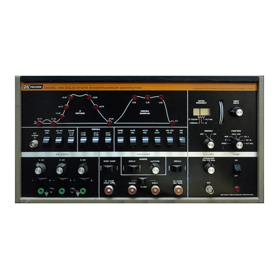
Controls and Outputs
Equipment Interconnection and Set-Up Procedure
Use of Model 415 Controls
Compensation for Poor Low Frequency Response of the Oscilloscope
Television Alignment
Using the Customer Option Oscillator
Using the Spare Marker Oscillator Asa Variable Frequency Source
Television Receiver Alignment Using the Model 415
Simplified Procedure for Diagnosing Need for Alignment
Analyzing the Response Curves
General Alignment Information
Localizing Alignment Problems
Alignment Methods
6.3.2.1 Tuner Link
Chroma Alignment
I-F Alignment
Information
Recording Alignment Reference
Alignment Touch-Up Procedures
Preliminary
Trap Adjustments
Mixer Injection
Chroma Circuit Adjustment
Tilt Adjustments, Antenna Injection
Complete 1-F and Chroma Alignment Procedure Using the Model
Trap Alignment Using Modulated Markers
PRE-ALIGNMENT of I-F BANDPASS COILS and TRANSFORMERS (When Specified)
TUNER LINK ALIGNMENT (When Specified)
Sweep Alignment of the 1-F Stages Using the Model 415
Chroma Circuit Alignment
Bandpass Amplifier Alignment Using Direct Video Sweep
Chroma Alignment Using Signal
Injection at the Antenna Terminals of
Points
Additional Television Alignment Procedures Using the Model 415
Tv Sound Alignment
Using the Model 415 in Television Sound Alignment
Automatic Fine Tuning (Aft)
Operation of Aft Circuits
Alignment of Aft Circuits
Condensed Work Guide
Manufacturers' Alignment Procedures Using the Model 415
Introduction
Alignment of Magnavox Model T933
Alignment of the Philco-Ford "S" Line Color Television Receiver
Other Uses of the Model 415
Alignment of Fm Receivers Using the Model 415
10.7 Mhz 1-F ALIGNMENT
Checking Fm Receiver Tracking
Variable Frequency Generator Calibration
Generators
Am Broadcast Receiver Tuning and Tracking Checks
Additional Uses of the Model 415
Model 415 Adjustments and Maintenance
Maintenance and Adjustment Procedures
Troubleshooting Information and Procedures
Interconnecting Cables, Test Leads and Switches
Regulated Power Supplies and Bias Supplies
Horizontal Sweep Circuits
PATTERN AMPLIFIER CIRCUITS (Ql9 and Q20)
Marker Detectors and Amplifiers
Video If/Rf Attenuator Q306
Use of Maintenance Information in Troubleshooting
Replacement of Defective Components
Internal Adjustment Procedures
Marker Oscillator Adjustments
Channel 4 Oscillator Adjustment
Channel 10 Oscillator Adjustment
PIX OSCILLATOR ADJUSTMENT (Bottom Cover of Model 415 Removed)
Using the Spare Mkr Oscillator
Using the Spare Marker as a
Using the Spare Mkr Oscillator Asa Crystal-Controlled Marker Oscillator
Variable Frequency Source
Adjustment of Sweep Oscillatorv Aractor Bias
BALANCING SWEEP OUTPUTS of HORIZONTA,LSWEEP AMPLIFIER Ql4
Calibration of the Spare Mkr
Frequency Operation
Oscillator for Variable
Sweep Linearity Adjustment
Advertisement
Quick Links
Download this manual
/Bftf
Model
415
.--------·-,-~-·----,
_j
Sweep/Marker Gener tor
A Product of DYNASCAN CORPORATION 1801 West Belle Plaine • Chicago, Illinois 130613 _ ,.....,...
PRICE $5.00
Table of
Contents
Previous
Page
Next
Page
1
2
3
4
5
Advertisement
Table of Contents
Troubleshooting
MODEL 415 ADJUSTMENTS AND MAINTENANCE
85
MARKER DETECTORS AND AMPLIFIERS
87
Need help?
Do you have a question about the 415 and is the answer not in the manual?
Ask a question
Questions and answers
Related Manuals for B&K 415
Portable Generator B&K E-200D Instruction Manual
Rf signal generator (27 pages)
Related Products for B&K 415
B&K Reference 4420
B&K Reference 4430
B&K 4416
B&K 466
B&K E-200D
Table of Contents
Print
Rename the bookmark
Delete bookmark?
Delete from my manuals?
Login
Sign In
OR
Sign in with Facebook
Sign in with Google
Upload manual
Upload from disk
Upload from URL


Need help?
Do you have a question about the 415 and is the answer not in the manual?
Questions and answers