Advertisement
Quick Links
th
DL7MAJ, Oct 20
2015
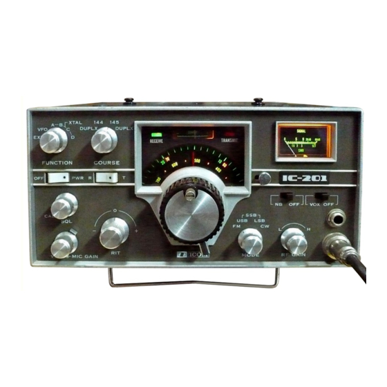
ICOM IC-201 Allmode Transceiver
Alignment Procedure
Please note: This procedure is reengineered by myself and may be not in accordance with
the original procedure from the manufacturer!
So I can´t accept any claims from anybody in case of injuries, problems, damages and losses.
Usage of this procedure is at own risk!
Of course you may ask me or give hints for improvement.
Page 1 (21)
Advertisement

Subscribe to Our Youtube Channel
Related Manuals for Icom IC-201


Summary of Contents for Icom IC-201
- Page 1 DL7MAJ, Oct 20 2015 ICOM IC-201 Allmode Transceiver Alignment Procedure Please note: This procedure is reengineered by myself and may be not in accordance with the original procedure from the manufacturer! So I can´t accept any claims from anybody in case of injuries, problems, damages and losses.
- Page 2 DL7MAJ, Oct 20 2015 1) Mode „USB“ 2) No microphone connected; „MIC GAIN“ control to CCW 3) „VOX“ On 4) Adjust R50 that VOX doesn´t trip (search for the point where VOX trips without Modulation and set R50 shortly before this point. 5) Check that for all modes (FM, USB, LSB, CW)VOX doesn’t trip without modulation 6) “CAL”...
- Page 3 DL7MAJ, Oct 20 2015 1) Receive “R” 2) Connect Counter (AC-coupled) to Emitter of Q14. Best use analog scope with Y- output 3) Mode “USB” adjust C61 to 10,69850 MHZ (X1) 4) Mode “LSB” adjust C66 to 10,70150 MHz (X2) 5) There may be some interaction so repeat 3 and 4 if necessary 6) Mode “CW”...
- Page 4 DL7MAJ, Oct 20 2015 Page 4 (21)
- Page 5 DL7MAJ, Oct 20 2015 1) weak signal at 145,000MHz just enough to move S-Meter to S=5 2) Tune L1 Set “RF GAIN” to “H”; mac CW 3) Unmount RF-Module (two clamps at each end) 4) Tune in to L7 for maximum; L2 to L5 are only accessible from bottom 5) Mount RF-Module 6) If a big increase of sensitivity has been achieved, then repeat adjustment of S-Meter (Look for GIF, step 14)
- Page 6 DL7MAJ, Oct 20 2015 Premix 1) “CAL” (Calibrator) switched off 2) Receive “R”, mode USB 3) Connect Counter (AC-coupled) to Collector of Q3. Best use analog scope with Y- output 4) Connect DC-Voltmeter or Scope with 10:1 probe to common cathodes of D4 and D5. 5) “RIT”...
- Page 7 DL7MAJ, Oct 20 2015 Page 7 (21)
- Page 8 DL7MAJ, Oct 20 2015 FM-IF Alignment of FM-Unit can only be done outside the transceiver. Use pins to connect supply (9V), Gnd, signals and meters acc. to the picture. IMPORTANT: An external trimmer R1 (10kOhm) has also to be connected, otherwise Q1 wouldn´t operate.
- Page 9 DL7MAJ, Oct 20 2015 Page 9 (21)
- Page 10 DL7MAJ, Oct 20 2015 T-MIX 1) Alignment requires an sweeper 2) Coarse “145MHz” *) 3) Connect sweeper to the external VFO input: J2 pins 8 (Gnd) and 9 4) Set sweep to 10,000 to 13,000MHz, app. 0dBm (700mVpp) *) 5) Mode “FM” 6) 50...
- Page 11 DL7MAJ, Oct 20 2015 Final/PA 1) “Coarse” to 145MHz, VFO to 000 (equals 145,000MHz) 2) Remove heatsink from rear of PA-unit (from now on observe it´s temperature) 3) Connect Dummyload 50W and Powermeter to antenna output 4) Remove jumper P11 from J11 5) “CW”, unkeyed 6) Connect A-meter between pin 2 &...
- Page 12 DL7MAJ, Oct 20 2015 Page 12 (21)
- Page 13 DL7MAJ, Oct 20 2015 Remove plug, connect A-meter Page 13 (21)
- Page 14 DL7MAJ, Oct 20 2015 1) Let the VFO warm up for app. 10 Minutes 2) Adjust tuning range of VFO with L1 to exactly 1000kHz (use internal calibrator as reference) 3) If you adjust L1, a realignment of the mechanical scale is necessary. 4) Repeat 3) and 3) if necessary Be very careful! Use plastic trimmers only –...
- Page 15 DL7MAJ, Oct 20 2015 (De-) Installation of the VFO, Sequence Page 15 (21)
- Page 16 DL7MAJ, Oct 20 2015 Page 16 (21)
- Page 17 DL7MAJ, Oct 20 2015 Page 17 (21)
- Page 18 DL7MAJ, Oct 20 2015 Page 18 (21)
- Page 19 DL7MAJ, Oct 20 2015 Page 19 (21)
- Page 20 DL7MAJ, Oct 20 2015 Page 20 (21)
- Page 21 DL7MAJ, Oct 20 2015 If you want to contact the author: Stefan Steger, DL7MAJ, eMail: dl7maj@darc.de Homepage: www.dl7maj.de Page 21 (21)
Need help?
Do you have a question about the IC-201 and is the answer not in the manual?
Questions and answers