Advertisement
OPTIONAL ELECTRIC ELEMENT
INSTALLATION
(15 or 20 kW)
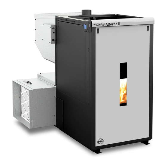
CADDY ALTERNA II FURNACE
This manual is available for free download on the manufacturer's web site. It is a copyrighted document.
Re-sale is strictly prohibited. The manufacturer may update this manual from time to time and cannot be
responsible for problems, injuries, or damages arising out of the use of information contained in any
manual obtained from unauthorized sources.
45819A
Printed in Canada
13-08-2015
Advertisement
Table of Contents

Summary of Contents for Stove Builder International CADDY ALTERNA II
- Page 1 INSTALLATION (15 or 20 kW) CADDY ALTERNA II FURNACE This manual is available for free download on the manufacturer’s web site. It is a copyrighted document. Re-sale is strictly prohibited. The manufacturer may update this manual from time to time and cannot be responsible for problems, injuries, or damages arising out of the use of information contained in any manual obtained from unauthorized sources.
- Page 2 OPTIONAL ELECTRIC ELEMENT INSTALLATION Your Caddy Alterna II furnace can be installed with an optional electric element (15 or 20 kW). This option can be installed on either side of your furnace (right or left). The installation must be performed by a qualified professional.
- Page 3 Remove the panel from the electric element box (D). Keep the screws (C). CAUTION: Before installing the unit inside the furnace, it is advised to do the wiring connections of the element and its connection to the power board (See Appendix A). Please note that in order to use a single circuit breaker for the electrical unit and the power board, it is possible to hook up the power board from the electric element (see Appendix B).
- Page 4 secure electric element box in place, use the six screws (A) included with the electric unit. Secure the panel from the electric element box (D) with the 8 screws (C) kept from step 2.
- Page 5 Annexe A Electrical wiring and power board connections Use two wires (18 ga) (not included). Skinned at both ends. Connect the 2 wires to the « EHT » terminal of the power board up to the terminal on the electrical element. Hook up the main electrical supply to terminal L1, N, L2, G located on the electrical element.
- Page 6 (F) that is included with the electric element box. For the electrical connection and the connection to the power board please follow the 3 steps in Appendix A. STOVE BUILDER INTERNATIONAL INC. 250, de Copenhague, Saint-Augustin-de-Desmaures (Quebec), Canada G3A 2H3 Tel: (418) 878-3040 Fax: (418) 878-3001...
Need help?
Do you have a question about the CADDY ALTERNA II and is the answer not in the manual?
Questions and answers