Table of Contents
Advertisement
Quick Links
Please observe protection
note ISO 16016.
DATAFLEX
Torque Measuring Shaft
Operating/Assembly instructions
DATAFLEX
Torque measuring shaft type 42/1000
Drawn:
2017-01-02 Shg/Koe
Verified:
2017-01-02 Shg
®
42/1000
®
Replaced for:
Replaced by:
KTR-N
49016 EN
Sheet:
1 of 21
Edition:
2
KTR-N dated 2015-04-13
Advertisement
Table of Contents

Subscribe to Our Youtube Channel
Summary of Contents for KTR-Group DATAFLEX 42/1000
- Page 1 ® DATAFLEX 42/1000 KTR-N 49016 EN Torque Measuring Shaft Sheet: 1 of 21 Operating/Assembly instructions Edition: ® DATAFLEX Torque measuring shaft type 42/1000 Drawn: 2017-01-02 Shg/Koe Replaced for: KTR-N dated 2015-04-13 Please observe protection note ISO 16016. Verified: 2017-01-02 Shg Replaced by:...
-
Page 2: Table Of Contents
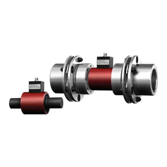
® DATAFLEX 42/1000 KTR-N 49016 EN Torque Measuring Shaft Sheet: 2 of 21 Operating/Assembly instructions Edition: ® DATAFLEX is a maintenance-free torque measuring shaft with integrated speed measurement. Com- ® bined with the steel lamina coupling RADEX -N the complete system forms a torsionally stiff, double- cardanic coupling with integrated measuring shaft. -
Page 3: Technical Data
® DATAFLEX 42/1000 KTR-N 49016 EN Torque Measuring Shaft Sheet: 3 of 21 Operating/Assembly instructions Edition: Technical data ® DATAFLEX torque measuring shaft ® Illustration 1: DATAFLEX torque measuring shaft Table 1: Dimensions ® DATAFLEX Dimensions [mm] type 42/1000 84.7 18.5 Table 2: Technical data ®... - Page 4 ® DATAFLEX 42/1000 KTR-N 49016 EN Torque Measuring Shaft Sheet: 4 of 21 Operating/Assembly instructions Edition: Technical data ® ® DATAFLEX torque measuring shaft in combination with RADEX ® ® Illustration 2: DATAFLEX with RADEX Table 3: Dimensions and technical data ®...
-
Page 5: Advice
® DATAFLEX 42/1000 KTR-N 49016 EN Torque Measuring Shaft Sheet: 5 of 21 Operating/Assembly instructions Edition: Advice 2.1 General advice Please read through these operating/assembly instructions carefully before you start up the measuring shaft. Please pay special attention to the safety instructions! The assembly instructions are part of your product. -
Page 6: Intended Use
® DATAFLEX 42/1000 KTR-N 49016 EN Torque Measuring Shaft Sheet: 6 of 21 Operating/Assembly instructions Edition: Advice 2.4 Intended use You may only assemble, operate and maintain the measuring shaft if you have carefully read through the assembly instructions and understood them ... -
Page 7: Assembly
® DATAFLEX 42/1000 KTR-N 49016 EN Torque Measuring Shaft Sheet: 7 of 21 Operating/Assembly instructions Edition: Assembly The measuring shaft and the couplings are supplied as single pre-assembled component assemblies. Before assembly the measuring shaft has to be inspected for completeness. ®... -
Page 8: Advice For Finish Bore
® DATAFLEX 42/1000 KTR-N 49016 EN Torque Measuring Shaft Sheet: 8 of 21 Operating/Assembly instructions Edition: Assembly 4.2 Advice for finish bore The maximum permissible bore diameters d 1max ® STOP (see RADEX -N catalogue) must not be exceed- 2max ed. -
Page 9: Assembly Of The Hubs
® DATAFLEX 42/1000 KTR-N 49016 EN Torque Measuring Shaft Sheet: 9 of 21 Operating/Assembly instructions Edition: Assembly 4.3 Displacements - alignment of the torque measuring shaft Table 4: Displacement figures ® DATAFLEX Max. axial displace- Max. radial displacement Max. angular displace- ®... -
Page 10: Assembly Of Hubs On The Driving And Driven Side
® DATAFLEX 42/1000 KTR-N 49016 EN Torque Measuring Shaft Sheet: 10 of 21 Operating/Assembly instructions Edition: Assembly ® 4.5 Assembly of the RADEX -N clamping ring hubs on the ® DATAFLEX torque measuring shaft Illustration 7: Assembly of clamping ring hubs Illustration 8: Adjusting to dimension L Table 5: Tightening torques of clamping screws ®... -
Page 11: Assembly Of Lamina Sets
® DATAFLEX 42/1000 KTR-N 49016 EN Torque Measuring Shaft Sheet: 11 of 21 Operating/Assembly instructions Edition: Assembly 4.7 Assembly of lamina sets With the assembly please make sure that the lamina sets are installed free from distortion in axial direction. Disregarding this advice may cause damage to the coupling. ... -
Page 12: Advice For Assembly Of The Dataflex
® DATAFLEX 42/1000 KTR-N 49016 EN Torque Measuring Shaft Sheet: 12 of 21 Operating/Assembly instructions Edition: Assembly ® 4.9 Advice for assembly of the DATAFLEX torque measuring shaft Fixing the housing The housing must be protected from rotation. For that purpose there is a thread size M4 at the bottom side. - Page 13 ® DATAFLEX 42/1000 KTR-N 49016 EN Torque Measuring Shaft Sheet: 13 of 21 Operating/Assembly instructions Edition: Assembly 4.10 Technical description 2. Connection housing DF2 The connection housing DF2 has 12 screw terminals to connect power supply, display equipment and switches. The torque signal is displayed as proportional direct voltage from 0 …...
- Page 14 ® DATAFLEX 42/1000 KTR-N 49016 EN Torque Measuring Shaft Sheet: 14 of 21 Operating/Assembly instructions Edition: Assembly 4.10 Technical description b) Torque signal M-U (No. 4 and 5) The output voltage is proportional to the torque with an output of values between -10V and 10V. Table 8 shows the relation between torque and output voltage.
- Page 15 ® DATAFLEX 42/1000 KTR-N 49016 EN Torque Measuring Shaft Sheet: 15 of 21 Operating/Assembly instructions Edition: Assembly 4.10 Technical description d) Speed signals N1, N2, N-U, R/L (No. 1, 3, 7, 9) The connection housing DF2 has 4 connections for speed output: Two square-wave signals shifted by 90 de- grees (N1, N2) A scalable voltage output (N-U) with direction...
- Page 16 ® DATAFLEX 42/1000 KTR-N 49016 EN Torque Measuring Shaft Sheet: 16 of 21 Operating/Assembly instructions Edition: Assembly 4.10 Technical description Output circuit (connection N1 and N2) The speed outputs N1 and N2 have short-circuit proof push- pull outputs providing a square-wave voltage with an ampli- tude of 24V and a maximum switching current of 30 mA.
- Page 17 ® DATAFLEX 42/1000 KTR-N 49016 EN Torque Measuring Shaft Sheet: 17 of 21 Operating/Assembly instructions Edition: Assembly 4.10 Technical description Outputs N-U and R/L The KTR connection housing DF02 has an integrated f/U converter which converts the square wave signals of the en- coder into a linear DC voltage output (terminal N-U) and pro- duces an additional signal for the rotational direction (terminal R/L).
- Page 18 ® DATAFLEX 42/1000 KTR-N 49016 EN Torque Measuring Shaft Sheet: 18 of 21 Operating/Assembly instructions Edition: Assembly 4.10 Technical description e) Control buttons and LEDs (No. 12 to 14 and illustration 22) The connection housing DF02 contains control switches and LEDs for offset adjustment and sensor test. For reasons of safety the sensor test can only be performed during the first 15 seconds after switching on.
- Page 19 ® DATAFLEX 42/1000 KTR-N 49016 EN Torque Measuring Shaft Sheet: 19 of 21 Operating/Assembly instructions Edition: Assembly 4.10 Technical description Manual zero adjustment The zero point of the torque output can be adjusted manually. For this purpose both push buttons T1 and T2 are activated simultaneously for 2 seconds.
-
Page 20: Disposal
® DATAFLEX 42/1000 KTR-N 49016 EN Torque Measuring Shaft Sheet: 20 of 21 Operating/Assembly instructions Edition: Disposal In respect of environmental protection please dispose of the packaging or products on termination of their service life in accordance with the legal regulations and standards that apply, respectively. Maintenance and service ®... -
Page 21: Ec Certificate Of Conformity
® DATAFLEX 42/1000 KTR-N 49016 EN Torque Measuring Shaft Sheet: 21 of 21 Operating/Assembly instructions Edition: EC Certificate of conformity EC Certificate of conformity The manufacturer - KTR Systems GmbH, D-48432 Rheine - states that the ® DATAFLEX torque measuring shaft described in the present operating instructions is in accordance with the following directive: 2004/108/EC council directive of 15 December 2004 on the approximation of the...
Need help?
Do you have a question about the DATAFLEX 42/1000 and is the answer not in the manual?
Questions and answers