Sign In
Upload
Download
Table of Contents
Contents
Add to my manuals
Delete from my manuals
Share
URL of this page:
HTML Link:
Bookmark this page
Add
Manual will be automatically added to "My Manuals"
Print this page
×
Bookmark added
×
Added to my manuals
Manuals
Brands
Leprecon Manuals
Control Panel
LP612
User manual
Leprecon LP612 User Manual
Hide thumbs
1
2
Table Of Contents
3
4
5
6
7
8
9
10
11
12
13
14
15
16
17
18
19
20
21
22
23
24
25
26
27
28
29
30
31
page
of
31
Go
/
31
Contents
Table of Contents
Bookmarks
Table of Contents
Table of Contents
Setup
Power Requirements
Microplex Output
DMX Output
Analog Output
Connector Pin Assignments : Lp612 Only
Connector Pin Assignments : Lp624 Only
Control Layout
Startup
Manual Mode
Xandy Preset Scenes
Crossfader
Master
Bump Buttons
Running in Manual Mode
Patching Dimmers
Using Memory Presets
Clearing Memory
Preset Menu: LP612 ONLY
Preset Menu: LP624 ONLY
Page Freeze
Recording Presets into Memory
Preset Playback
Previewing Presets
Editing Presets
Cue Stack
Recording Stack Scenes
Assigning Fade Times
Default Fade Time
Stack Playback
Editing Cues
Chase
Pattern
Step
Rate
Pre-Programmed Chases
Recording New Chases
Level Chases: LP624 Only
Pattern Edit
Step Edit
Repair and Warranty Information
Advertisement
Quick Links
1
Power Requirements
2
DMX Output
3
Microplex Output
4
Patching Dimmers
5
Clearing Memory
Download this manual
R
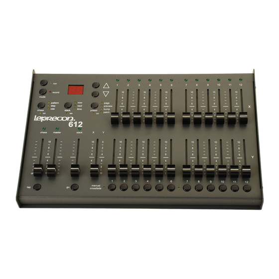
LP612 and LP624 User's Manual
Rev. 1.2
LP612 Software Version 1.1
LP624 Software Version 1.0
Leprecon/CAE, Inc
P.O. Box 430, 10087 Industrial Drive, Hamburg, MI 48139-0430 810-231-9373, FAX 810-231-1631
Copyright CAE, Inc. January 1997, Publication # 21-2125D
Table of
Contents
Previous
Page
Next
Page
1
2
3
4
5
Advertisement
Table of Contents
Need help?
Do you have a question about the LP612 and is the answer not in the manual?
Ask a question
Questions and answers
Related Manuals for Leprecon LP612
Control Panel Leprecon LP624 User Manual
(31 pages)
This manual is also suitable for:
Lp624
Table of Contents
Print
Rename the bookmark
Delete bookmark?
Delete from my manuals?
Login
Sign In
OR
Sign in with Facebook
Sign in with Google
Upload manual
Upload from disk
Upload from URL


Need help?
Do you have a question about the LP612 and is the answer not in the manual?
Questions and answers