Advertisement
Quick Links
Advertisement

Summary of Contents for Atlantis Splash Tech R60 2nd Stage
- Page 1 Tech R60 2nd Stage Service Manual TECH R60 2nd STAGE...
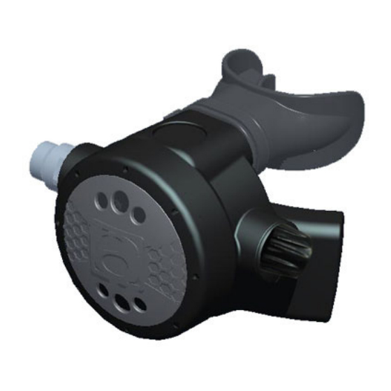
- Page 2 ATLANTIS TECH R60 2ND STAGE These models are balanced demand valve second stage regulators - smaller and lighter than most other primary second stages. They provide breathing gas as you demand it with low inhalation resistance. Breathing effort is factory set to the average performance level required by most divers.
- Page 3 SPECIFICATIONS ATLANTIS TECH R60 ADJ SECOND STAGE REGULATOR INHALATION RESISTANCE 0.9” - 1.4” (2.3 - 5.08 cm) w.c. @ 1 atmosphere EXHALATION RESISTANCE 0.6” (1.52 cm) w.c. max. @ 1 atm. RECOMMENDED LUBRICANT LTI Christo-Lube MCG 129�� B. AS-201 ADJ SECOND STAGE REGULATOR...
- Page 4 REVISION DESCRIPTION DATE APPR ECN NO RELEASE 2011/06/16 ANNUAL SERVICE REPLACEMENT PARTS:...
- Page 5 0177 EXHAUST VALVE 0180 EXHAUST COVER 0185 DIAPHRAGM 0199 DIAPHRAGM WASHER 0188 COVER RING - ALUMINUM 0329 PURGE BUTTON-ATLANTIS 0191 ADJUST KNOB 1-78-19-01 O-RING BALANCE CHAMBER 0174 BALANCE CYLINDER 0181 SPRING 3-9532-01 O-RING...
- Page 6 3.0 SERVICE KIT LIST RO-17 SERIAL BALANCE 2ND STAGE REG SERVICE KIT PART NO DESCRIPTION Q’TY 1- 78-19-01 O-RING 3-9532 O-RING 0193 LP SEAT 2- 015-01 O-RING 2- 010-01 O-RING 2- 019-01 O-RING 3.1 SERVICE TOOL LIST TOREQE WRENCH ADJUST TOOL TORQUE WRENCH 18MM HEX SOCKET O-RING TOOL SEAT...
- Page 7 SERVICE PROCEDURES FOR THE TECH R60 ADJ Before you begin disassembly of the regulator, test the first and second stages for output pressures 'work of breathing' and leakage. Pre-testing in this way will help the technician to pinpoint any specific problems requiring repair.
- Page 8 SERVICE PROCEDURES FOR THE TECH R60 ADJ The work area must be clean and well lit, with clean compressed air available to blow sand and dirt from parts.
- Page 9 TOOLS REQUIRED FOR 2ND STAGE SERVICING - 18MM HEX Wrench - Adjust tool for second stage - 2nd Stage Service Kit - Clean Shop Rags - Dow-Corning Compound 111 Silicone Grease or - LTI Christo-Lube MCG 129 - IP Gauge - O-ring picks - Soapy spray - Magnehelic Gauge...
- Page 10 ble wrenches to loosen the hose nut from the the hose assembly from the second stage. y for any cuts or cracks, especially on the hose Use the 6” and 8” adjustable wrenches to loosen the hose nut from the COUPLING (12). nd Remove and discard the O-rings from each Remove the hose assembly from the second stage.
- Page 11 Put the exhaust cover (5) into hot water for a moment. Remove the exhaust cover (5) from the housing by pulling it back.
- Page 12 Before removing the exhaust valve (4) from the housing (3), bend the valve over as far as it will go from the top, bottom, left, and right sides. If it fails to snap back quickly, and does not lie perfectly flat against the housing exhaust grid, the valve should be replaced. If it does snap back satisfactorily, remove it by pulling it out with your fingers.
- Page 13 Unscrew the cover ring (8) from the housing (3). If the cover is difficult to remove you can try several methods to loosen it; Heat the 2nd stage body surrounding the Ring by running hot water from a tap over it. When the plastic is hot, it will expand and loosen the threads.
- Page 14 Remove the DIAPHRAGM WASHER (7) and the diaphragm (6) from the housing (3).
- Page 15 For future reference, look at the lever (20) at this time. Notice how the pivot end of the lever is held into the inlet tube (18) by two plastic flanges on the housing. Note this positioning for re-assembly.
- Page 16 Hold the diaphragm up to a light source. Gently stretch the diaphragm and look for tears or pinholes. If any are found, replace the diaphragm. Loosen and remove the nut (26) from the inlet tube (18) Remove the plastic bushing (25) from the inlet tube. Remove and discard the O-ring (17) from the inlet tube.
- Page 17 Depress the lever (20) fully onto the inlet tube. Grasp the tab of the Venturi Lever (23). While pulling on the Venturi Lever (23), push the inlet tube assembly out of the housing (3). Remove the Venturi Lever (23) from the valve tube assembly. Remove and discard the O-ring (24) from the Venturi Lever (23).
- Page 18 Turn the ADJUST KNOB (10) counterclockwise to remove it from the inlet tube. Remove and discard the O-ring (11). The balancing chamber (12), spring (13) and poppet (15) are removed at this time. They will often fall out if the adjust tube is tipped on its end. Remove and discard the O-ring (17) from the outside of the inlet tube (18).
- Page 19 The lever (20) should not be removed from the inlet tube unnecessarily. However, it can be removed by carefully springing out one of the feet and pivoting it over the inlet tube. Do not over-bend the lever legs. Straighten the legs if they are bent outward from parallel. Remove and discard the LP seat (16) from the poppet (15).
- Page 20 After the threads are disengaged, remove the orifice (22) from the inlet tube (18) by pulling and turning counterclockwise at the same time or inserting a soft blunt ended instrument from the other end. Remove and discard the O-ring (21) from the orifice.
-
Page 21: Commonly Used Cleaning Solutions
CLEANING AND INSPECTION OF THE 2nd STAGE Rinse all plastic and silicone parts in fresh warm soapy water solution. Rinse with clean warm water and then blow the parts dry with compressed air to remove any sand and dust particles. DO NOT use vinegar or other acid solutions on the plastic parts since this will cause the plastic to become brittle! If necessary because of deposits or corrosion, clean all metal parts of the second stage in an... - Page 22 Inspect the housing (3) for any cracks or nicks. Look particularly closely at the area where the exhaust valve (4) seals and where the bushing (25) clamps. Replace the housing if any cracks are found. Inspect the sealing surface on the orifice (22) (where the seating seat seals) for any nicks or scratches.
- Page 23 Inspect the exhaust valve (4). Look carefully at the base of the barbed nipple where it comes out of the middle of the valve. Look for any tearing at this point. Replace the valve if any tears are found. Replace the valve if nicks or tears are found at the sealing edges of the valve. During an Annual Overhaul, all parts included in the Annual Service Kit are replaced no matter what the condition of those parts.
- Page 24 PRELIMINARY ASSEMBLY OF THE SECOND STAGE Ensure that all parts are clean. Before installing new O-rings into the regulator, lightly lubricate the O-rings with Dow-Corning 111 Silicone Grease or LTI Christo-Lube MCG 129.
- Page 25 Install the exhaust valve (4) into the case by inserting the nipple into the square hole from the outside of the case. Reach inside the case and pull the nipple firmly with the fingers until you hear or feel it “click” into place. Inspect the exhaust valve to see that it is properly seated.
- Page 26 Install a new O-ring (17) onto the outside of the inlet tube (18). If the lever (20) was removed, carefully re-fit it into the inlet tube (18). To orient the lever properly, hold the inlet tube with the external threads to the right. Turn the inlet tube until you can see the hole where the air exits the valve tube.
- Page 27 Insert the new seating LP seat (16) into the white poppet (15). Install the lubricated small O-rings (14) onto the poppet tip. Install the spring (13) onto the poppet and the balance chamber (12) onto the poppet to make the shuttle valve assembly.
- Page 28 Insert the poppet assembly. Push the assembly all of the way into the inlet tube. The first thing that might hang up on the tabs of the lever is the LP seat. Wiggle the lever to get this past the tabs. When the “¬” shaped feet get to the lever tabs they will lift the lever inwards as you push the assembly in.
- Page 29 Install a new well lubricated O-ring (11) onto the ADJUST KNOB (10).
- Page 30 Insert the ADJUST KNOB (10) into the inlet tube over the poppet assembly you just installed. Turn the ADJUST KNOB (10) clockwise until the O-ring and flange have passed the hole where the pin (19) is installed. Install the pin (19) into the inlet tube (18). Back the ADJUST KNOB (10) out until it tightens against the pin (19), holding it in place.
- Page 31 Install the new O-ring (24) onto the Venturi Lever (23). While holding the tabs in place in the inlet tube with two fingers, depress the lever (20) and the slide the Venturi Lever (23) into place on the inlet tube (18).
- Page 32 Install the inlet tube assembly into the housing (3). After assembly, make sure that the pivot end of the lever is held into the inlet tube (18) by two plastic flanges on the housing just as they did when you took the housing apart (see step 4.2.7).
- Page 33 Install the O-ring (17) over the external threaded end of the inlet tube (18). Install the bushing (25) (flat side facing the body) over the external threaded end of the inlet tube. Install the nut (26) over the external threaded end of the inlet tube. Tighten the nut snuggly 1-2 ft/lb (2-3 Nm) with a wrench.
- Page 34 Use the ADJUST TOOL to insert the orifice into the inlet tube. Turn adjust knob left so the adjust knob is set in minimum position. Adjust knob keep on “Min”. Adjust the orifice (22) with the ADJUST TOOL. It is important that the final adjustment leaves the lever with about 1/8”...
- Page 35 Put the exhaust cover (5) into the hot water for a moment. Install the exhaust cover (5) onto the body by pushing firmly. Do not twist the cover on! Install the diaphragm (6) into the housing (3) so that it sits evenly on the ledge. Install the diaphragm washer (7) over the diaphragm.
- Page 36 SET-UP OF THE SECOND STAGE Connect the inline adjustment to inlet nipple. Note: Attach the second stage to the overhauled and properly adjusted first stage that it is going to be used with, mounted on an air tank filled to the maximum pressure the regulator is going to be used with.
- Page 37 Carefully turn the air on. There should be no air leaking from the second stage with proper intermediate pressure applied to the hose. Turn the inline adjustment tool left until you hear a small leak and then turn the adjustment tool right until leaking stops. Then turn the adjustment tool a further 1/8th of a turn to the right.
- Page 38 Work the lever up and down a few times while the regulator is pressurised by purging. Each time the lever is released, no air hissing should be heard. After reaching the proper pressure setting, push the purge cover on the second stage again several times and watch how the intermediate pressure reading responds.
- Page 39 Re-check work of breathing. Replace mouthpiece with cable tie.
-
Page 40: Helpful Hints
5.0 HELPFUL HINTS 5.1 TROUBLESHOOTING POSSIBLE CAUSE RECOMMENDED ACTION Inlet filter clogged. Replace the filter. Air supply to 1st stage Verify the supply air pressure. Make insufficient. sure the customer had the air valve turned all the way on during the dive. 2nd stage improperly adjusted. - Page 41 B. CREEPING INTERMEDIATE PRESSURE: POSSIBLE CAUSE RECOMMENDED ACTION Damaged or worn 1st Replace 1st stage stage C. HISSING FROM SECOND STAGE (but intermediate pressure is OK): POSSIBLE CAUSE RECOMMENDED ACTION Damaged or worn 2nd stage LP seat Replace LP seat (16) Nicked orifice (22) sealing surfaces Replace orifice...
- Page 42 E. HIGH FREQUENCY HUMMING OR BUZZING DURING INHALATION: POSSIBLE CAUSE RECOMMENDED ACTION Harmonic resonance between the Change the 1st stage springs and other 1st stage components. F. LOW FREQUENCY FLUTTERING DURING INHALATION (Above the surface only): POSSIBLE CAUSE RECOMMENDED ACTION Harmonic resonance between Remove, rotate and re-install diaphragm or the springs and other 2nd...
Need help?
Do you have a question about the Splash Tech R60 2nd Stage and is the answer not in the manual?
Questions and answers