Table of Contents
Advertisement
Quick Links
Advertisement
Table of Contents

Summary of Contents for Wanner International OCWI 34 1
- Page 1 INSTALLATION & SERVICE MANUAL Oil Cooler – OCWI 34 1 Wanner International Ltd 8-9 Fleet Business Park Sandy Lane, Church Crookham Hampshire GU52 8BF England United Kingdom www.wannerint.com email: sales@wannerint.com Tel: +44(0)1252 816 847 WI 04/15 rev 2, JK...
-
Page 2: Oil Cooler
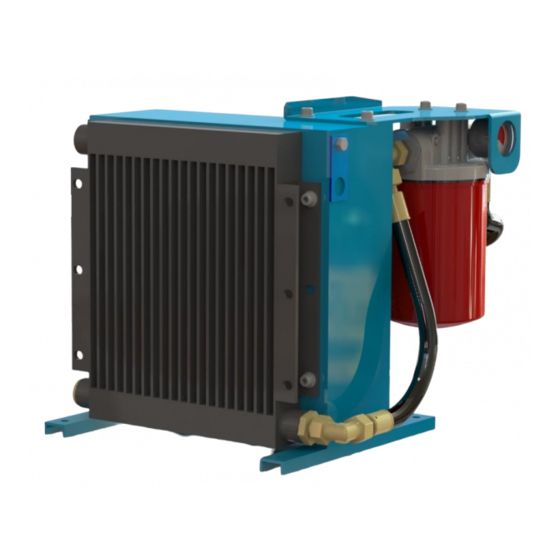
OIL COOLER INTRODUCTION The WANNER oil cooler, OCWI 34 1 has been developed for use with Hydra-Cell pumps (G10, G25, G35); specifically for use in high temperature applications to maintain the correct oil viscosity to ensure good lubrication of pump bearings and other mechanical elements. -
Page 3: Important Guidelines
IMPORTANT GUIDELINES The oil cooler must not be used for any purpose other than cooling oil in accordance with the guidelines and instructions set out in this operator’s manual. Check that once installed, the operating conditions of the oil cooler cannot be exceeded. -
Page 4: Installation
INSTALLATION Before a successful installation can be assured, the following points need to be followed carefully. A qualified technician should always install the unit. The oil cooler needs to be positioned as close as possible to the pump being cooled. The hoses are 1.5 metres long. -
Page 5: Electrical Connections
TECHNICAL SPECIFICATIONS Motor specification – OCWI 34 1 – 0.37 Kw, 1ph, 4-pole (1450 rpm), IP 65, fitted with thermistors. Figure 1, Wiring connections Pump – Gear pump, delivers 2.6 l/m at 1450 rpm Cartridge filter –... -
Page 6: Commissioning Procedure
COMMISSIONING PROCEDURE PRIMING THE OIL COOLER CIRCUIT At this point the immediate area around the pump and oil cooler installation should be prepared for an amount of oil spillage as this will be inevitable and may cause a slip hazard! The oil cooler must be filled with the same oil as in the pump, in accordance with the following procedure. - Page 7 PRIMING THE OIL COOLER CIRCUIT (continued) The oil cooler is entirely filled with oil when the flow from the hose is free of air bubbles. Switch off the oil cooler. The oil level in the pump should be at the level of the baffle plate inside the top of the pump to allow for heat expansion of the oil.
-
Page 8: Cleaning And Maintenance
CLEANING AND MAINTENANCE. ROUTINE MAINTENANCE. This is purely a guideline. Individual operating conditions should determine the true interval. For further advice contact WANNER. When the oil cooler is operating under correct conditions and is installed correctly, it will require little maintenance. The following inspections and maintenance checks are recommended. - Page 9 HOSE KIT ASSEMBLIES Part number 1BT/6-12 3/8 Hose assembly GE12LRFOA BRASS CAP ASSY. 5B/10-4 (G10 only) 5B/10-6 (G25 & G35) 5/8 Hose assembly 1BT/10-12 Z11B/6-6-6 (OC HK 2) Z11B/10-10-10 (OC HK 2) Two hose kits are available to be used only in conjunction with the Wanner oil cooler. OC HK 1 –...
Need help?
Do you have a question about the OCWI 34 1 and is the answer not in the manual?
Questions and answers