
Related Manuals for WAREMA climatronic Tableau Interface Series

Summary of Contents for WAREMA climatronic Tableau Interface Series
- Page 1 WAREMA climatronic Tableau Interface ® Installation instructions (Keep for future use) Valid from 1 July 2009 Sonne. Licht. WAREMA . 890358_a...
- Page 2 Imprint WAREMA Renkhoff SE Hans-Wilhelm-Renkhoff-Strasse 2 97828 Marktheidenfeld/Main Germany WAREMA and the WAREMA logo are trade marks of WAREMA Renkhoff All other brand or product names included in this document are trade marks or registered trade marks of their respective owners.
-
Page 3: Table Of Contents
Content Table of contents Characteristics ....................4 Safety instructions ................... 5 Meanings of symbols and pictographs ............5 Intended use ......................6 Targeted reader group ..................6 Retrofitting and modifications ................7 Mounting, connection and repairs ..............8 Additional documentation ...................9 Maintenance......................9 Liability ........................9 Installation ...................... 10 Mounting the device .................. -
Page 4: Characteristics
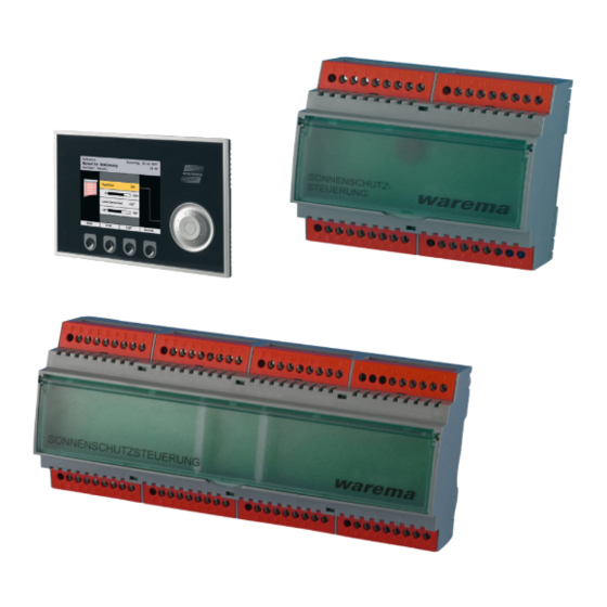
1 Characteristics The WAREMA climatronic Tableau Interface enables the connection of ad- ® ditional switches and push buttons to a WAREMA climatronic system. It can ® be used to implement control panels for operating the equipment connected to the climatronic ®... -
Page 5: Safety Instructions
WAREMA climatronic Tableau Interface ® 2 Safety instructions We developed and tested the WAREMA climatronic Tableau Interface in ® compliance with the basic safety requirements. Nonetheless, some risks remain. For this reason, please read these instructions before setting up and operat- ing the control. -
Page 6: Intended Use
2.2 Intended use The WAREMA climatronic Tableau Interface is used to connect switches and ® push buttons. The input data are read in by the WAREMA climatronic via the ® climabus. The device is designed for interior installation. The approval of the manufacturer must be obtained for uses outside of the purposes listed here. -
Page 7: Retrofitting And Modifications
WAREMA climatronic Tableau Interface ® Mounting and commissioning may therefore only be performed by properly trained qualified technicians. These technicians must be able to recognize sources of danger that may be caused by the mechanical, electrical or elec- tronic equipment! Persons mounting or connecting the device must know and have understood the content of these instructions. -
Page 8: Mounting, Connection And Repairs
WAREMA climatronic Tableau Interface ® 2.5 Mounting, connection and repairs AANER Danger to life through electrical voltage! Connecting, maintenance or repair work on the electrical parts of the entire system must only be performed when power to the system has been cut off, unless otherwise described. -
Page 9: Additional Documentation
Number WAREMA climatronic operating instructions 890033 Installation instructions WAREMA climatronic 890034 WAREMA climatronic studio software manual 816467 2.7 Maintenance There are no parts within the device that require maintenance. 2.8 Liability Failure to comply with the product information in these instructions and use... -
Page 10: Installation
WAREMA climatronic Tableau Interface ® 3 Installation This chapter will tell you where and how the individual components must be installed. WARAIAN Hazardous conditions and malfunctions are possible! The device and its auEiliary components may only be operated when installed and at the specified installation locations. -
Page 11: Mounting The Device
WAREMA climatronic Tableau Interface ® 3.1 Mounting the device The devices are designed for installation in a distributor or for surface-mount- ed installation. They are to be mounted in a dry and readily accessible loca- tion. The devices absolutely must not be mounted outdoors and must not be subjected to direct sunlight. - Page 12 WAREMA climatronic Tableau Interface ® Fig. 4 Tableau Interface S in a 6 HP DIN rail-mounted housing 106 mm / 6 TE Fig. 5 Dimensions of 6 HP DIN rail-mounted housing We reserve the right to carry out improvements 890358_a•en•18.06.2009...
-
Page 13: Surface Mounting
WAREMA climatronic Tableau Interface ® 3.1.2 Surface mounting Please observe the cable types recommended in the wiring diagrams. Fig. 6 Tableau Interface M in a surface-mounted housing * 4M: 132mm 6M: 184mm ** 4M: 158mm 6M: 210mm 119 mm 184 mm*... - Page 14 WAREMA climatronic Tableau Interface ® Fig. 8 Tableau Interface S in a surface-mounted housing 119 mm 80 mm 60 mm 106 mm 180 mm Fig. 9 Dimensions of Tableau Interface S surface-mounted housing Open the terminal covers as described for Tableau Interface M (see ).
-
Page 15: Connection
WAREMA climatronic Tableau Interface ® 4 Connection 4.1 Connection information WARAIAN In a permanently routed installation, there must be an in-series disconnecting and isolating device to separate the device from the supply voltage (switch according to TEN 60335-1, Section 25.2, e.g. circuit breaker). -
Page 16: Hardware Settings On The Tableau Interfaces
WAREMA climatronic Tableau Interface ® 4.2 Hardware settings on the Tableau Interfaces The additionally connected Tableau Interfaces S must be enabled at the Tableau Interface M to be addressed via the slave bus. This is accomplished using the encoding switches on the Tableau Interface M printed circuit board. - Page 17 WAREMA climatronic Tableau Interface ® Terminal TEncoding Setting Comment strip switch Tableau Interface M Address 1 is not queried Address 1 is queried Address 2 is not queried Address 2 is queried Address 3 is not queried Address 3 is queried...
-
Page 18: Wiring Diagrams
WAREMA climatronic Tableau Interface ® 5 Wiring diagrams Fig. 13 Tableau Interface M: All connections at a glance We reserve the right to carry out improvements 890358_a•en•18.06.2009... - Page 19 Communication (clima- Inputs bus RS485) Commissioning Logs the Tableau Inter- Push buttons Prog ID face on to the WAREMA climatronic® Common potential Lights up when the Prog ID button is pressed,flashes when LTED bus communication with WAREMA climatronic ®...
- Page 20 WAREMA climatronic Tableau Interface ® Tableau Interface S Fig. 15 Tableau Interface S: All connections at a glance We reserve the right to carry out improvements 890358_a•en•18.06.2009...
- Page 21 WAREMA climatronic Tableau Interface ® Tableau Interface S Terminal Identifica- Terminal Identifica- Terminal Comment Terminal Comment strip tion strip tion Connections for switches and push buttons Commissioning Common potential Display of the address status, lights up when LTED the adjusted address is...
- Page 22 WAREMA climatronic Tableau Interface ® For the Tableau Interfaces M supply, we recommend, independent of the line length X5:Input X6:RS485 Prog and number of units, mounting a 0V 24V ID LED P 25 26 27 28 29 5V separate power supply unit.
- Page 23 WAREMA climatronic Tableau Interface ® Maximum line length per push button: 500 m. All common terminals P are bridged in the Tableau Interface. X1: 1 X2: 9 10 11 12 13 14 15 16 Fig. 19 Connection of switches and push buttons 890358_a•en•18.06.2009...
-
Page 24: Commissioning
WAREMA climatronic Tableau Interface ® 6 Commissioning The Tableau Interface M can be set up directly on the control panel. The inputs are managed using the PC software. The Assistant does not provide support with commissioning and parameter settings. NOTTE The Tableau Interface M itself manages the Tableau Interface S, which can be up to four in number. - Page 25 WAREMA climatronic Tableau Interface ® Click on the [Create tableau with Prog button] menu item. The following display appears: Press the Prog ID button on the Tableau Interface M. The LED to the right of the button lights up. The Tableau Interface M logs onto the climatronic with its serial number.
- Page 26 WAREMA climatronic Tableau Interface ® 6.2 Loading the Tableau Interface Return to the [Configuration] menu level by pressing the [Back] button Start menu twice. Main menu Settings Select [Load data to devices]. Authorised Dealer Project planning ...
-
Page 27: Displaying The Input Assignments
NOTTE The menu merely serves as a display; the Tableau Interfaces can only be configured via the WAREMA climatronic studio software. Additional information can be found in the WAREMA climatronic studio soft- ware manual. 890358_a•en•18.06.2009 We reserve the right to carry out improvements... -
Page 28: Technical Data
WAREMA climatronic Tableau Interface ® 7 Technical data 7.1 Tableau Interface M Tableau Interface M Min. Typ. MaE. Unit 24 V DC supply Operating voltage V DC Power consumption Number of inputs Inputs for switches/push but- Pieces tons Shared terminals (P) -
Page 29: Tableau Interface S
WAREMA climatronic Tableau Interface ® 7.2 Tableau Interface S Tableau Interface S Min. Typ. MaE. Unit 24 V DC supply Operating voltage V DC Power consumption Number of inputs Inputs for switches/push but- Pieces tons Shared terminals (P) Pieces TEnclosure Dimensions See Figs. - Page 30 WAREMA climatronic Tableau Interface ® Aotes We reserve the right to carry out improvements 890358_a•en•18.06.2009...
- Page 31 WAREMA climatronic Tableau Interface ® Aotes 890358_a•en•18.06.2009 We reserve the right to carry out improvements...
- Page 32 Keep in a safe place for use during commissioning! Affix the ID label of the Tableau Interfaces here. Note down the installation location here. Notes for commissioning (e.g. special features concerning mounting position, wiring, etc.): WAREMA Renkhoff SE http://www.warema.de info@warema.de Hans-Wilhelm-Renkhoff-Strasse 2...
Need help?
Do you have a question about the climatronic Tableau Interface Series and is the answer not in the manual?
Questions and answers