Table of Contents
Advertisement
Quick Links
SUN
READ THIS INSTRUCTION MANUAL THOROUGHLY BEFORE
INSTALLING, OPERATING, SERVICING OR MAINTAINING THE
INSTALLING OPERATING SERVICING OR MAINTAINING THE
MODEL: ALIGNMENT EELR124A /
SUN is a trademark of
Snap-on Tools
Corporation
1-800-268-7959
®
LIFT. SAVE THIS MANUAL.
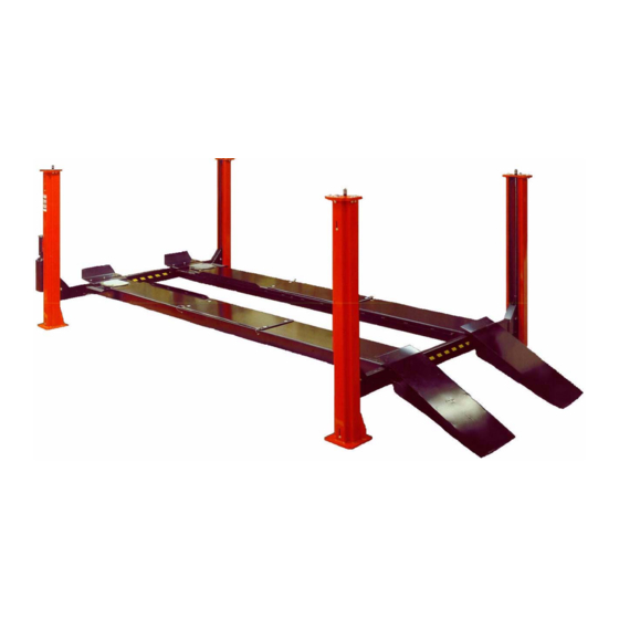
KODIAK QUAD RACK
EELR124APKG
SERVICE WHE18406
18000 LB
INSTALLATION
INSTALLATION
and OPERATION
and OPERATION
d OPERATION
d OPERATION
MANUAL
MANUAL
JUL 2010
REV.-
6-1787
Advertisement
Table of Contents

Related Manuals for Sun Microsystems ALIGNMENT EELR124A

Summary of Contents for Sun Microsystems ALIGNMENT EELR124A
- Page 1 READ THIS INSTRUCTION MANUAL THOROUGHLY BEFORE INSTALLING OPERATING SERVICING OR MAINTAINING THE INSTALLING, OPERATING, SERVICING OR MAINTAINING THE LIFT. SAVE THIS MANUAL. KODIAK QUAD RACK MODEL: ALIGNMENT EELR124A / EELR124APKG SERVICE WHE18406 18000 LB SUN is a trademark of Snap-on Tools...
- Page 2 THE FOLLOWING APPLIES TO ALL LIFTS IMPORTANT SAFETY INSTRUCTIONS When using this lift, basic safety precautions should always be followed, including the following: Read all instructions in this manual and on the lift thoroughly before installing, operating, servicing or maintaining the lift. Inspect lift daily.
-
Page 3: Table Of Contents
TABLE OF CONTENTS PAGE GENERAL SPECIFICATION ..............4 TOOLS REQUIRED FOR INSTALLATION..........5 CONTENTS ....................6 INSTALLATION INSTRUCTIONS .............. 7 4.1 Chalk Line Layout ..............9 4.2 Front And Rear Crossmember Assemblies ......10 4.3 Power Pack Installation............14 4.4 Hydraulic Installation .............. 14 4.5 Electrical Connections ............ -
Page 4: General Specification
1.0 GENERAL SPECIFICATION Maximum Capacity: 18,000 lb. 8,165 kg Overall Length: 304-7/8” 7468mm Overall Width: 152-1/8” 3864mm Down Position Height: 9-1/2” 241mm Maximum Lifting Height: 72” 1829mm Maximum Wheel Base: 210” 5334mm Power Rating: 208-230 Volts, 1Ph., 20 Amp, 60Hz. Air Requirements: 90 –... -
Page 5: Tools Required For Installation
CHECK CONTENTS OF ACCESSORY BOX WITH THE PACKING LIST ENCLOSED ATTENTION! This lift is intended for indoor installation only. It is prohibited to install this product outdoors. Operating environment temperature range should be 41 – 104 °F (5 – 40 °C). Failure to adhere will result in decertification, loss of warranty, and possible damage to the equipment. -
Page 6: Contents
3.0 CONTENTS The lift is packaged to protect it from any damage that may occur during shipping. The two deck assemblies and crossmembers are packaged together with the accessory boxes strapped to them. Main Structural Components: 1 - Left Side Deck Assembly (complete with hydraulic cylinder, sheaves and cables) 1 - Right Side Deck Assembly 1 - Front Crossmember Assembly (with air cylinder release locks and... -
Page 7: Installation Instructions
INSTALLATION INSTRUCTIONS PLEASE TAKE THE TIME TO READ THESE INSTRUCTIONS COMPLETELY. A QUICK CHECK OF THE CONTENTS OF THE ACCESSORY BOX WOULD ALSO DECREASE THE INSTALLATION TIME. • Gather the tools and materials required for the installation. • Select the location best suited for your lift. NOTE: In determining lift area check for the following: Ease of driving a vehicle on and off the lift. - Page 8 TYPICAL BAY LAYOUT 8 of 42...
-
Page 9: Chalk Line Layout
CHALK LINE LAYOUT Figure 1. Chalk line layout • Refer to Figure 1. Make a chalk line parallel to the doorway at least 322-7/8” in from the doorway. This will be the location for the front face of the tower baseplate. Call this line "A". -
Page 10: Front And Rear Crossmember Assemblies
4.2 FRONT AND REAR CROSSMEMBER ASSEMBLIES IMPORTANT NOTE: To determine the front, rear, left side and right side of the decks check the following: • The left side deck has the hydraulic cylinder mounted to its underside and includes the cables. The work steps, attached to the turn plate pocket cutouts, are located at the front of the lift and should point outward when installed. - Page 11 • Remove the left and right deck assemblies from their packaging and place them on axle stands as follows (see Figure 1): - Place the left deck assembly so that the inside edge lies along chalk line “B” - Place the right deck assembly so that the inside edge lies along chalk line “C” - Position both decks so that the front edge lies along chalk line “A”...
- Page 12 removed and lying at each corner of the lift. Before proceeding, check that the layout matches that shown in Figure 1, that the lift is square and that there is a 40” gap between the decks along their entire length. Figure 3.
- Page 13 • Place the Glide Bearings (located in the accessory box) on the slider block weldments and bolt the slider block weldments back onto the crossmember using the 3/8”-16UNC x 1”LG Hex HD Bolts and 3/8” Lockwashers removed previously. • Replace all of the crossmember pulleys, being sure to lock the sheave pins with the 3/8”-16UNC x 1”LG Hex HD Bolt.
-
Page 14: Power Pack Installation
POWER PACK INSTALLATION NOTE: WHEN WORKING WITH HYDRAULIC LINES AND VALVES, IT IS IMPORTANT TO KEEP ALL COMPONENTS CLEAN AND FREE OF DIRT. Up control Button Filler Cap Connection for hydraulic fitting assembly Breather Screw Do not remove blue plastic cap. -
Page 15: Electrical Connections
• Connect the end of the flexible hydraulic hose (3/8" JIC, F SWIVEL) to the fitting at the cylinder. DO NOT OVER TIGHTEN. • Connect the other end of the flexible hydraulic hose (3/8" JIC, F SWIVEL) to the flow control on the powerpack. ELECTRICAL CONNECTIONS CAUTION: ALL ELECTRICAL CONNECTIONS SHOULD BE MADE BY A QUALIFIED ELECTRICIAN. -
Page 16: Air Installations
AIR INSTALLATIONS NOTE: FOR ALL AIR INSTALLATIONS REFER TO THE HYDRAULIC AND AIR KITS DIAGRAM IN THE PARTS MANUAL. • Install the air valve and filter assembly (found in the accessory box) to the mounting bracket on the power post. To do this pull off the pushbutton and unscrew the plastic nut. -
Page 17: Anchor Installation
ANCHOR INSTALLATION • Check all layout dimensions in the General Specifications (pg. 4) and Figure 1 before continuing with anchor installation. 1. Refer to Figure 7 while reading through these instructions. Figure 7. Anchor installation 2. Ensure that the lift is fully supported by the cables and is at a level just above the work stands. -
Page 18: Deck Leveling Procedure
4 FT LEVEL Figure 8. Floor slope Figure 9. Post leveling NOTE: THE 3/4” × 5 ½” LG. WEDGE ANCHOR BOLTS SUPPLIED MUST HAVE A MINIMUM EMBEDMENT OF 3¼” INTO CONCRETE FLOOR. NOTE: IN CASES WHERE THE FLOOR IS EXTREMELY OUT OF LEVEL, THE MECHANICAL SAFETIES MAY NOT ENGAGE ON THE SAME LOCK. - Page 19 • When flush with the safety shoe, tighten the two (2) 5/8"-11 UNC hex nuts at the top of each safety ladder and the 3/8"-16 UNC × 1"LG hex bolts at the bottom and top of each safety ladder (on the back side of the tower). •...
-
Page 20: Final Check Of Assembled Lift
4.10 FINAL CHECK OF ASSEMBLED LIFT Final dimension check after anchoring. ____ Check for air and hydraulic leaks. ____ Ensure cables are properly routed and free from obstructions. ____ Ensure all safety lock mechanism are working correctly. ____ Re-check level of post and decks. ____ Makes sure ramps are secured correctly with cotter pins ____... -
Page 21: Operation Test With Vehicle
4.11 OPERATION TEST WITH VEHICLE Lower lift to ground. Drive vehicle on to lift, install wheel chocks. Raise lift to and lower onto 3-4 lock positions during full rise to ensure all locks are working correctly. Double check level of runways, front to rear and side to side while on locks. Re-adjust cables if necessary while vehicle is on. -
Page 22: Safety And Operating Instructions
5.0 SAFETY AND OPERATING INSTRUCTIONS 1. Inspect the lift daily. Do not operate if malfunctions occur or damaged parts have been found. 2. Never attempt to overload the lift. The manufacturer's rated capacity is shown on the serial number tag on the power post. 3. -
Page 23: Safety Awareness
SAFETY AWARENESS AUTOMOTIVE LIFT INSTITUTE (ALI) 23 of 42... -
Page 24: Recommended Maintenance
7.0 RECOMMENDED MAINTENANCE DAILY Check general operation of lift. Check operations of mechanical safety locks. Check operation of air release valve for air leaks. Check operation of cables and pulleys. Check and drain water trap filter bowl. MONTHLY Check anchor bolts (if loose re-torque to 150 ft. lbs.). Replace concrete if anchors continue to loosen. -
Page 25: Parts List
8.0 PARTS LIST LIFT ASSEMBLY 25 of 42... -
Page 26: Parts List - Lift Assembly
PARTS LIST – LIFT ASSEMBLY ITEM QTY. DESCRIPTION PART # TOWER WELDMENT - POWER POST 4-0636 TOWER WELDMENT 4-0630 FRONT CROSSMEMBER WELDMENT 4-0627 REAR CROSSMEMBER WELDMENT 4-0626 DECK WELDMENT - L.S. (ALIGNMENT) 4-0629 DECK WELDMENT – L.S. (SERVICE) 4-0916 DECK WELDMENT - R.S. (ALIGNMENT) 4-0628 DECK WELDMENT –... -
Page 27: Tower Assembly
TOWER ASSEMBLY 27 of 42... -
Page 28: Parts List - Power Tower Assembly
PARTS LIST – POWER TOWER ASSEMBLY ITEM QTY. DESCRIPTION PART # POWER PACK, 230V/1PH 6-1695 POWER PACK, 230V/3PH 6-2615 POWER POST WELDMENT 4-0636 SAFETY RACK WELDMENT 3-0581 HEX NUT, 5/8”-11UNC, GR8 6-0673 FLAT WASHER, 3/4" I.D. 6-0738 HEX HD. BOLT, 3/8”-16UNC X 1”LG., GR.8 6-0668 LOCK WASHER, 3/8”... -
Page 29: Deck Assembly (Left Side)
DECK ASSEMBLY (LEFT SIDE) 29 of 42... -
Page 30: Parts List - Deck Assembly (Left Side)
PARTS LIST – DECK ASSEMBLY (LEFT SIDE) ITEM QTY. DESCRIPTION PART # DECK WELDMENT - L.S. (ALIGNMENT) 4-0629 DECK WELDMENT - L.S. (SERVICE) 4-0916 HEX HD BOLT, 3/8"-16UNC x 1" LG 6-0668 LOCKWASHER, 3/8" 6-0058 DECK SHEAVE PIN WELDMENT 2-1355 SHEAVE SPACER, 1"... -
Page 31: Crossmember Assembly
CROSSMEMBER ASSEMBLY 31 of 42... -
Page 32: Parts List - Crossmember Assembly
PARTS LIST – CROSSMEMBER ASSEMBLY ITEM QTY. DESCRIPTION PART # FRONT CROSSMEMBER WELDMENT 4-0627 REAR CROSSMEMBER WELDMENT 4-0626 "CAUTION" TAPE, 40" LONG 6-1125 SHEAVE ASSEMBLY 2-1377 NYLON THRUST WASHER 1-0757 SHEAVE SPACER, 3/8" LONG 1-0786 LOCK SAFETY PIN WELDMENT 1-1744 COTTER PIN, 1/8"... -
Page 33: Cylinder Assembly
CYLINDER ASSEMBLY 33 of 42... -
Page 34: Parts List - Cylinder Assembly
8.10 PARTS LIST – CYLINDER ASSEMBLY ITEM QTY. DESCRIPTION PART # CYLINDER TUBE WELDMENT 4” BORE 2-1345 PISTON ROD - MACHINED 2-1340 ORING, 4”OD x 1/8”C/S 6-1633 BACKUP RING 6-1634 GLAND 3-0673 ROD SEAL, 1½”ID x 1 7/8”OD x 1/4” 6-1892 ROD WIPER, 1½”ID x 1 7/8”OD x 3/16”... -
Page 35: Hydraulic And Air Kit
8.11 HYDRAULIC AND AIR KIT 35 of 42... -
Page 36: Parts List - Hydraulic And Air Kit
8.12 PARTS LIST – HYDRAULIC AND AIR KIT ITEM QTY. DESCRIPTION PART # 90° ELBOW, 1/8" NPT x 1/4" POLYTUBE 6-0709 AIR CYLINDER 6-0651 10FT 1/4" DIA. POLY TUBE 6-1396 ADAPTER, 3/8" POLY TUBE x 1/4" NPT 6-0710 TERMINAL BOLT, 3/4" 6-0713 PLUG, 1/4"... -
Page 37: Cable Routing
8.13 CABLE ROUTING 37 of 42... -
Page 38: Parts List - Cable Routing
8.14 PARTS LIST – CABLE ROUTING ITEM QTY. DESCRIPTION PART # CABLE ASSY. 407.5” - FRONT LEFT 2-1360 CABLE ASSY. 473.5” - FRONT RIGHT 2-1361 CABLE ASSY. 162” - REAR LEFT 2-1362 CABLE ASSY. 228” - REAR RIGHT 2-1363 HEX NUT, 7/8”-14UNF GR5 6-0724 CABLE SPACER, 2”LG 1-0800... -
Page 39: Power Pack Assembly
8.15 POWER PACK ASSEMBLY 39 of 42... -
Page 40: Parts List - Power Pack
8.16 PARTS LIST – POWER PACK ITEM QTY. DESCRIPTION PART # MICROSWITCH AND WIRING ASSEMBLY, 1PH 6-0881 MICROSWITCH AND WIRING ASSEMBLY, 3PH 6-0918 MICROSWITCH BOOT 6-1084 MOTOR, 230V AC, 1 PHASE, 60 HERTZ 3HP 6-1959 MOTOR, 230V AC, 3 PHASE, 60 HERTZ 6-1079 MOTOR ADAPTER KIT 0-0197... - Page 41 CAUTION ALL SAFETY LADDERS USED ON 4-POST LIFTS ARE PRELOADED. REMOVING THE BOLT HOLDING THE BOTTOM PORTION OF THE SAFETY LADDER WITHOUT PROPER PRECAUTIONS CAN RESULT IN INJURY. PLEASE CONTACT CUSTOMER SERVICE FOR PROPER REMOVAL INSTRUCTIONS. 41 of 42...
-
Page 42: Available Accessories
AVAILABLE ACCESSORIES Hydraulic Jack Beams Premium Air / Standard Air / Hydraulic Jack Hydraulic Jack Beam Beam 4500 lb, 6000 lb, 7000 lb 6000 lb, 7000 lb Other Accessories Drive-On Ramp Air Outlet Kit Extension for (Factory Low Profile Installed) Vehicle (set of 2) Sliding Waste...
Need help?
Do you have a question about the ALIGNMENT EELR124A and is the answer not in the manual?
Questions and answers