Advertisement
Available languages
Available languages
Quick Links
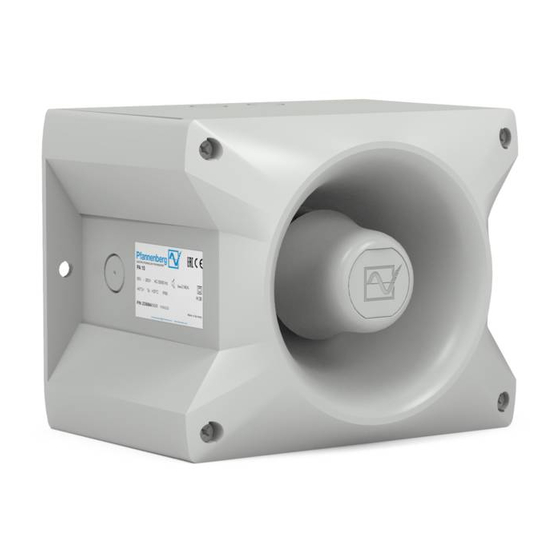
PA 10/20
Maße
214 [8.44"]
190 [7.48"]
M20-Ausbruch vorbereitet/
Prepared M20 cut-out
37 [1.46"]
PA 10/ PA 20
Technische Daten
PA 10
Nennschallpegel
110dB (A) 1m 120dB (A) 1m
Lautstärkeregelung
-10dB
Töne
Blitzenergie
Blitzfolgefrequenz
Bemessungs-
Spannung
(Begrenzungen
siehe Zulassungen)
Spannungsbereich
Stromaufnahme
Schallgeber (max.)
[mA]
Stromaufnahme
Blitzleuchte (max.)
[mA]
Leistungsaufnahme
Einschaltdauer
Anschlussklemmen
Schutzart
Schutzklasse
Betriebstemperatur
Lagertemperatur
Max. rel.Luftfeuchte
Kabeleinführung
Dichtbereich der
Durchführungstülle
Gehäusematerial
Haubenmaterial
Einbaulage
Optionen
Zubehör
Haubenfarben
985 501 002
PA X 10-10/ PA X 10-15
Betriebs- und Montageanleitung
L
37 [1.46"]
Bohrbild im Inneren
89.4 [3.52"]
des Gehäuses
70.7 [2.78"]
35.4
[1.39"]
64.2 [2.53"]
86 [3.39"]
PA 20
-9dB
-
-
0,14 - 2,5mm² feindrähtig / AWG24 - AWG 14 (stranded)
7x M20 vorgeprägt
7 – 13 mm
Bei Verwendung von Kabeldurchmessern < 7 mm ist eine Kabelverschraubung
-
Kartoninhalt:
1x Alarmgerät
1x Membrannippel M20
1x Betriebsanleitung
1x Widerstand (nur –SSM)
PA X 10-10/ PA X 10-15
PA X 20-10/ PA X 20-15
PA X 10-10
PA X 10-15
110dB (A) 1m
-10dB
80
10J
15J
100%
IP66 (EN60529), Type 4 & 4x
II
-40° C...+55° C
-40° C...+70° C
90%
mit ausreichender Schutzart vorzusehen
PC/ABS Blend
PC
beliebig
-SSM, (siehe Seite 5)
Plombierstopfen (Art-Nr. 28300000002)
klar, weiß, gelb, orange, rot, grün, blau
PA X 20-10/ PA X 20-15
L
L
PA X 20-10
120dB (A) 1m
10J
1Hz
5x M20 vorgeprägt
37 [1.46"]
190 [7.48"]
214 [8.44"]
PA X 20-15
-9dB
15J
1
Advertisement

Related Manuals for Pfannenberg PA 10

Summary of Contents for Pfannenberg PA 10
- Page 1 89.4 [3.52"] des Gehäuses 70.7 [2.78"] 35.4 [1.39"] 37 [1.46"] 190 [7.48"] 214 [8.44"] PA 10/ PA 20 PA X 10-10/ PA X 10-15 PA X 20-10/ PA X 20-15 64.2 [2.53"] 86 [3.39"] Technische Daten PA 10 PA 20...
- Page 2 660Hz (Unterbrochener Ton/ Intermittent) 800Hz/ 1000Hz (Wechselton/ Alternating) 544Hz/ 440Hz (NF S 32-001) EN54-3: siehe Dokumente Signalisierungsbereich 30305-005-1 (PA 10) und 30306-005-1 (PA 20) Umweltschutzklasse Typ B Die Prüfung erfolgte unter Verwendung des mitgelieferten Membrannippels und der äußeren Befesti- gungsbohrungen.
- Page 3 (without rectifier) Lautstärkeregler Hinweis: Um EN54-3 konform zu sein, muss sich der Lautstärkeregler in der folgenden Position befinden: PA 10: in Maximalposition PA 20: in der werksmäßig eingestellten und gesicherten Position (Auswahl der Polarität der Tonartenschalter Steuerspannung für C1 und C2)
- Page 4 Änderung der Töne durch externe Ansteuerung Für Anwendungen, die zusätzlich zum Grundton weitere Töne benötigen, besteht die Möglichkeit, bis zu drei weitere Tonarten mithilfe der folgenden elektrischen Ansteuerungen zu erreichen. Grundsätzlich wird erst der gewünschte Grundton ♪ (siehe Tonartentabelle im Anhang) mit dem Tonartenschalter S3 auf der Treiberplatine eingestellt.
- Page 5 Option –SSM (Soft-Start-Modul) (nur 24V DC): - Begrenzung der Einschaltstromspitze auf max. 2,1A (PA 10-SSM) bzw. 4,5A (PA 20-SSM, PA X 10-10-SSM, PA X 10-15-SSM, PA X 20-10-SSM, PA X 20-15-SSM). - Durchschalten der Betriebsspannung zum Betriebsmittel erst ab >7V - Widerstand zur Leitungsüberwachung angeschlossen...
-
Page 6: Technical Data
Prepared M20 cut-out 70.7 [2.78"] inside of housing 35.4 [1.39"] 37 [1.46"] 190 [7.48"] 214 [8.44"] PA 10/ PA 20 PA X 10-10/ PA X 10-15 PA X 20-10/ PA X 20-15 64.2 [2.53"] 86 [3.39"] Technical Data PA 10 PA 20... - Page 7 PA X 10 .. PA X 20 .. 230V AC PATROL-Sounders PA 10/ PA 20 comply with the limits for a Class B digital device, pursuant to part 15 of the FCC Rules. UL/ cUL specifications: Inrush current PA 10...
-
Page 8: Taking Into Operation
Taking into operation Safety notes: - Installation must be carried out by an electrician in compliance with the latest codes and regulations. - Danger: High voltage may be present. - Prior to opening, it must be ensured that no voltage is applied to the device. - Before electrical connection, the supply voltage on the type plate is to be checked. - Page 9 (without rectifier) To be EN54-3 compliant, the volume control has to be set to the following position: PA 10: Maximum position PA 20: in the secured factory setting position To be UL/cUL compliant, the volume control for PA 20 and PA X 20..
- Page 10 Change of the tones by external control For applications which require more tones than just the base tone, it is possible to provide up to three additional tone types with the use of the following electrical controls. As a basic rule, the desired base tone (♪, see tone table in the appendix) is set with the tone selector switch S3 on the driver board.
- Page 11 Option –SSM (Soft-Start-Module) (24V DC only): - Limitation of start-up peak: 2,1A for PA 10-SSM and 4,5A for 4,5A (PA 20-SSM, PA X 10-10-SSM, PA X 10-15-SSM, PA X 20-10-SSM, PA X 20-15-SSM) - Switching through the operating voltage to equipment: above 7V - Resistor for line monitoring mounted Operating voltage range: 18V –...
-
Page 12: Dados Técnicos
35.4 [1.39"] 37 [1.46"] 190 [7.48"] 214 [8.44"] PA X 10-10/ PA X 10-15 PA X 20-10/ PA X 20-15 PA 10/ PA 20 64.2 [2.53"] 86 [3.39"] Dados técnicos PA 10 PA 20 PA X 10-10 PA X 10-15... -
Page 13: Colocação Em Funcionamento
544 Hz/ 440 Hz (NF S 32-001) EN54-3: ver documentos Área de sinalização 30305-005-1 (PA 10) e 30306-005-1 (PA 20) Classe de proteção ambiental Tipo B O ensaio foi realizado usando o bico de membrana fornecido e os furos de fixação externos. - Page 14 Controle de volume Instrução: Para estar conforme com EN54-3, o controle de volume precisa estar na seguinte posição: PA 10: na posição máxima PA 20: ina posição ajustada de fábrica e fixada (Seleção da polaridade da Interruptor do tensão de controle para C1 e C2)
- Page 15 Alteração dos toques através do controle externo Para as aplicações que necessitam além do toque básico outros toques existe a possibilidade alcançar até três outros toques mediante os controles elétricos seguintes. Em princípio é ajustado primeiro o toque básico desejado ♪ (ver tabela dos tipos de toque no anexo) com o interruptor do tipo de toque S3 na placa de comunicação.
- Page 16 Opção –SSM (Soft Start Module/módulo de arranque suave) (só 24 V CC): - Limitação do pico de corrente inicial em, no máx., 2,1 A (PA 10-SSM) ou 4,5 A (PA 20-SSM, PA X 10-10-SSM, PA X 10-15-SSM, PA X 20-10-SSM, PA X 20-15-SSM).
- Page 17 Anhang/ Appendix/ Anexo (♪) Beschreibung/ Description/ Descrição „Tonartentabelle“ und „Ansteuerung der Töne“ Continuous, Finland All Clear 1500Hz „Tone table“ and „Selection of the tones“ Continuous 1200Hz „Tabela dos tipos de toque“ et „Controle dos toques“ Continuous, PFEER (Gas- 1000Hz alarm) Tonartentabelle/ Tone table/ Tabela dos tipos de toque Continuous, UK BS5839-1 950Hz...
- Page 18 Grund- Selector switch/ Interruptor do tipo de toque External Tone Control Beschreibung/ Description/ Descrição Ton-Nr. (Adjusting the base tone/ C1+C2 (♪) Ajuste do toque básico) Grund-Ton Tone Tone Tone (♪) 950Hz Intermittent, IMO (Telephone Call) 950Hz Intermittent, IMO (abandon ship) Intermittent, 2,5s 825Hz...
- Page 19 Pfannenberg GmbH · Werner-Witt-Straße 1 D- 21035 Hamburg · Tel.: +49/ (0)40/ 734 12-0 Fax: +49/ (0)40/ 734 12-101 05/2013 technical.support @pfannenberg.com 985501002 http://www.pfannenberg.com...
Need help?
Do you have a question about the PA 10 and is the answer not in the manual?
Questions and answers