Advertisement
Available languages
Available languages
Quick Links
Installation manual
CF1 - CF2
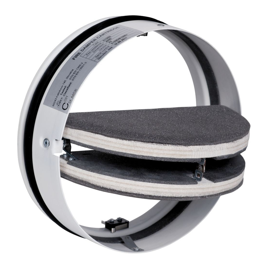
Cartridge Fire Damper
Cartridge-Brandschutzklappe
Cartouche coupe-feu
Vlinderbrandklep
Serranda tagliafuoco a cartuccia
EACH CARTRIDGE FIRE DAMPER HAS TO BE INSTALLED ACCORDING TO THIS MANUAL!
JEDE CARTRIDGE-BRANDSCHUTZKLAPPE SOLLTE NACH DIESEM MANUAL INSTALLIERT WERDEN!
TOUTE CARTOUCHE COUPE-FEU DOIT ETRE INSTALLEE CONFORMEMENT A CE MANUEL!
IEDERE VLINDERBRANDKLEP MOET WORDEN GEÏNSTALLEERD ZOALS OMSCHREVEN IN DEZE HANDLEIDING!
OGNI SERRANDA TAGLIAFUOCO A CARTUCCIA DEVE ESSERE INSTALLATA SECONDO QUESTO MANUALE!
1396 - CPD - 0055
GB - Original Installation, Operation and Maintenance manual (page 4-8)
DE - Die original Anleitung für Installation, Betrieb und Kontrolle (Seite 9-13)
FR - Manuel original d'installation, d'exploitation et de contrôle (pages 14-18)
NL - Originele Installatie-, Bedienings- en Onderhoudsvoorschriften (pagina 19-23)
IT - Manuale originale di installazione, uso e manutenzione (pagina 24-28)
www.aldes.com
Advertisement

Subscribe to Our Youtube Channel
Related Manuals for aldes CF1


Summary of Contents for aldes CF1
- Page 1 Installation manual CF1 - CF2 Cartridge Fire Damper Cartridge-Brandschutzklappe Cartouche coupe-feu Vlinderbrandklep Serranda tagliafuoco a cartuccia EACH CARTRIDGE FIRE DAMPER HAS TO BE INSTALLED ACCORDING TO THIS MANUAL! JEDE CARTRIDGE-BRANDSCHUTZKLAPPE SOLLTE NACH DIESEM MANUAL INSTALLIERT WERDEN! TOUTE CARTOUCHE COUPE-FEU DOIT ETRE INSTALLEE CONFORMEMENT A CE MANUEL! IEDERE VLINDERBRANDKLEP MOET WORDEN GEÏNSTALLEERD ZOALS OMSCHREVEN IN DEZE HANDLEIDING!
-
Page 2: Figures
1 - Die Mauer, 2 - Gips / Mörtel / Beton, 3 - Stahlrohr, 4 - CF1 - CF2, 5 - Ventil 1 - Paroi, 2 - Plâtre / mortier / bétón, 3 - Gaine acier, 4 - CF1 - CF2, 5 - Bouche ventilation 1 - Plafond, 2 - Plâtre / mortier / bétón, 3 - Gaine acier, 4 - CF1 - CF2, 5 - Bouche ventilation... -
Page 4: Table Of Contents
Introduction CF1 - CF2 contains basic information and recommendations regarding the design, installation and usage, which need to be followed in order to guarantee a proper and trouble-free operation of the unit. The key to this is to read this manual thoroughly, use the damper according to the instructions provided in it and to adhere to the safety requirements. -
Page 5: Installation Manual
1.2 Installation Into the End of a Duct with a Valve (see Fig. 2) CF1 - CF2 can be installed into a wall/ceiling at the end of a duct with a disc valve (the valve needs to be separately ordered from the ADP catalogue –... -
Page 6: Operation Manual
Unless stated otherwise, the operator checks the damper every 12 months. CF1 - CF2 is checked visually after having removed the disc valve from the duct end. If the damper is installed in a which facilitates the access inside the damper. - Page 7 Einführung Die Installation, Bedienung und Kontrolle Einleitung betrifft der Cartridge-Brandschutzklappen Type CF1 - CF2 EI60S, EI90S, EI120S, enthält Grundinformationen und Empfehlungen für die Installation und Verwendung die sind zu beachten für Störungsfreier Betrieb der Brandsutzklappe. Der Schlüssel zur ordnungsgemäßen und sicheren Betrieb der Einheit ist bestens Vertrauen mit dieser Anleitung, die Verwendung von Klappen in Übereinstimmung mit den darin enthaltenen Anweisungen, und die...
- Page 8 1.2 Installieren am Ende des Rohres for den Luft-Ventil (siehe Abbildung 2) CF1 - CF2 kann in die Wand / Decke am Ende des Rohres for den Luft-Ventil (Lösung - Ventil muss separat) installiert werden. Die Installation ist die gleiche wie in Abschnitt 1.1, wobei das Rohrende mit einem passenden Seite der Wand / Decke zusammenpassen muss, auf die das Ventil...
- Page 9 Brandschutzklappe einmal in 12 Monaten. Um CF1 - CF2 visuell zu überprüfen, den Luft-Ventile am Ende des Rohres wegzunehmen ist. Wenn die Cartridge-Brandschutzklappe in der Rohrleitung installiert wird, die durch die feuerresistente Wand leitet, wird für den Zugriff zu der Klappe in der Nähe der Wand auf Es ist zu kontrolieren die innenseite der Brandschutzklappe, thermische Sicherung, Dichtungen, Intumeszentband, Zustand der Bätter...
- Page 10 Introduction Ce manuel d’installation, d’exploitation et de contrôle concerne toutes cartouches coupe-feu type CF1 - CF2, EI60S, EI90S, EI120S. recommandations indiquées dans ce manuel. Pour assurer un bon foctionnement de l’unité, vous êtes tenus de prendre connaissance des instructions citées dans ce manuel et d’utiliser la cartouche coupe-feu conformément à...
- Page 11 être aligné avec la face du mur/plafond sur laquelle la bouche de ventilation sera installée. En installant la CF1 - CF2, il faut prévoir une distance de 50±10 mm entre le bout de la gaine et la zone où des lames en position de fermeture touchent les parois de la gaine. Suite à l’installation, les lames doivent être ouvertes vers l’intérieur de la gaine.
- Page 12 être réalisé tous les 12 mois. Le contrôle de la CF1 - CF2 se fait visuellement, suite au démontage de la bouche de ventilation du bout de la gaine. Si la cartouche de ventilation est installée à la gaine qui traverse la cloison coupe-feu, il est Lors du contrôle on examine également le corps interne de la cartouche coupe-feu, le fusible thermique, l’étanchéité...
- Page 13 Inleiding Deze Installatie-, Bedienings- en Onderhoudsvoorschriften hebben betrekking op vlinderbrandkleppen typen CF1 - CF2, EI60S, EI90S, EI120S, en bevatten basisinformatie en aanbevelingen over ontwerp, installatie en gebruik, die nageleefd moeten worden voor het correct en probleemloos functioneren van de brandklep. Lees daartoe deze voorschriften aandachtig door, gebruik de brandklep in overeenstemming met de voorschriften en leef alle veiligheidsvoorschriften na.
- Page 14 5. Controleer het functioneren van de brandklep (zie de Bedieningsvoorschriften) De CF1 - CF2 kan in een wand/plafond worden geïnstalleerd aan het uiteinde van een kanaal met behulp van een ventiel (dat apart moet worden besteld De installatie is hetzelfde als omschreven in hoofdstuk 1.1., waarbij erop gelet moet worden dat het uiteinde van het kanaal goed uitgelijnd blijft met die zijde van de wand/het plafond waar het ventiel geplaatst gaat worden.
- Page 15 7. controle of de eindschakelaar de open en gesloten positie goed aangeeft, correctie 8. controle of de brandklep in de standaard positie is verplaatst. De positie van de CF1 - CF2 -brandklep is correct als de bladen na afsluiting tussen de panelen vallen, die het externe oppervlak van de wand vormen. De ideale positie is als de bladen in het midden tussen deze panelen vallen.
- Page 16 Introduzione Manuale di installazione, funzionamento e manutenzione per serrande tagliafuoco a cartuccia CF1 - CF2, EI60S, EI90S, EI120S, contenente le informazioni di base e le raccomandazioni riguardanti la progettazione, l‘installazione e attentamente questo manuale e utilizzare la serranda secondo le istruzioni fornite per ottemperare ai requisiti di sicurezza.
- Page 17 CF1 - CF2 direzione del condotto. 1.3 Installazione delle CF1 - CF2 in una parete in cartongesso con lana minerale - Installazione a secco (vedi Fig. 3). 1. Per l‘installazione, fare una apertura circolare con un diametro minimo di Od + 60 mm nella parete.
- Page 18 Salvo diversa indicazione, l’operatore dovrà controllare la serranda ogni 12 mesi. CF1 - CF2 in un condotto che attraversa una parete ignifuga, per accedere alla serranda è necessario staccare il tubo vicino alla parete, sul lato dove E necessario controllare l‘involucro interno della serranda, il fusibile termico, la sigillatura, il prodotto schiumoso, la condizione della...
- Page 19 www.aldes.com...
Need help?
Do you have a question about the CF1 and is the answer not in the manual?
Questions and answers