Advertisement
Quick Links
Dicodes Flat Printed Circuit Board FL80_V2.1
(Preliminary, Subject to Change!)
The FL80 is an electronic circuit board for use in do it yourself electronic cigarettes, like box or tube
mods.
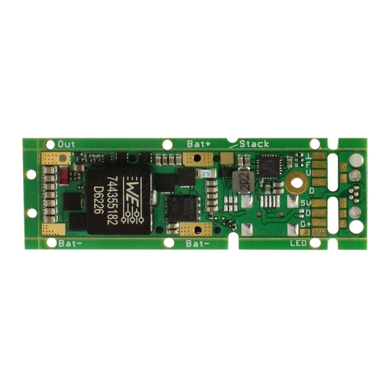
1. Size, Dimensions and Positions
The drawing below shows the overall size of dicodes FL80.
The board has several mounting options. When shipped, it has mounting strips on three sides,
each with several 2.1mm holes to mount it inside a housing using M2 screws or equivalent.
The mounting strips can be broken away individually. Without the strips the board has an
outline dimension of 17.2mm x 56.2mm (+-0.4mm due to break lines), or 17.2x63.7mm
respectively (with Micro-USB, see below).
There is also a separate metalized GND hole (battery minus), which gives the option to take
the GND connection from the housing if housing is connected to battery minus.
There are two USB connector option. One Mini-USB is on the bottom side of the board and
shows to the right, when you look at the board with the fire bottom in top position.
Note that the V2 boards default assembly is without the mini-USB plug populated (Beta
Version is always with mini-USB mounted).
The second option is to use the vertically mounted micro-USB plug on the extended part of the
PCB, which can be cut when not needed. The cut board has solder pads to reconnect it to the
main board with single wires. Such, the micro-USB board can be mounted elsewhere in the
housing.
Top-View
Drawing 1
Advertisement

Subscribe to Our Youtube Channel
Summary of Contents for dicodes FL80
- Page 1 Dicodes Flat Printed Circuit Board FL80_V2.1 (Preliminary, Subject to Change!) The FL80 is an electronic circuit board for use in do it yourself electronic cigarettes, like box or tube mods. 1. Size, Dimensions and Positions The drawing below shows the overall size of dicodes FL80.
- Page 2 On the FL80_V2 the Up-Button can have two different positions. One is the same as on the FL80_V1 (beta), option A, 3mm distance from the display frame. The second position is 2.5mm further away from the display frame, option B (total 5.5mm). This gives the option to use a rocker-button or larger up/down buttons.
- Page 3 “Stacking” Pad on the board (see picture above). Nevertheless, by using the dicodes dual/triple high efficiency battery balancer board, the charging of two batteries with the onboard charging circuitry is possible. Please follow the...
- Page 4 2.2. The On-Board USB-Charger The On-Board charging circuit is an active switch mode battery charger in contrast to the often used linear charger on other circuits. The active charger has the main advantage that it is much more efficient. This enables the circuit to charge with much higher currents compared to a linear charger, and thus charging the battery faster.
- Page 5 Drawing 4 The Jumper pads are on the bottom side of the board as shown in the picture above. To connect an external USB plug or an external charger either use the 6-pin FPC connection (default: not populated) on the top side of the board or connect cables to the solder pads on the bottom.
- Page 6 Drawing 5 The Pinning of the FPC connector is as follows: Pin 1 Vbus USB (+5V) Charger Supply Pin 2 Vbus USB (+5V) Charger Supply Pin 3 Used for Source Strength Detect Pin 4 Used for Source Strength Detect Pin 5 Pin 6 [Remark: Accidentially connecting a USB-source with a FFC cable to the Button FPC (External Buttons) does not harm the board.]...
- Page 7 Open the black lever of the FPC connector…. Attache the display cable top down into the FPC connector. Make sure the cable is straight and in end position. The flip the lever down as indicated by the arrow….
- Page 8 OLED directly to the onboard FPC, a standard 12pin 0.5mm pitch FFC cable can be connected to the board which is then connected to a display carrier board at the other end. Here is a picture of the display carrier board, dicodes offers:...
- Page 9 Drawing 6 The display is normally mounted in a black frame: Drawing 7 3.2. Buttons There are three buttons on the board: One bigger fire button “right” to the display, and two up/down buttons “left” to it. The up-button has two possible assembly positions. The default position is next to the OLED display, and the center of the button has a distance of 3mm to the plastic frame of the display, which is the default position.
- Page 10 Pin 1 Fire Button Pin 2 Up Button Pin 3 Down Button Pin 4 Reserved, do not connect Pin 5 Reserved, do not connect Pin 6 GND Accidentally connecting a FFC cable from an external button to the USB-FPC plug does not harm the board, but be careful: if J2 is closed and an external USB source is connected to the Mini-USB, although this should not be the configuration when J2 is closed, then, when pressing the Fire or the Up-button, the external source is shorted.
- Page 11 Wiring Battery and Atomizer...
Need help?
Do you have a question about the FL80 and is the answer not in the manual?
Questions and answers