
Summary of Contents for FIM 636
- Page 1 Istruzioni per il montaggio Installation instructions Montageanleitung FIM 636...
-
Page 3: Avvertenze Importanti
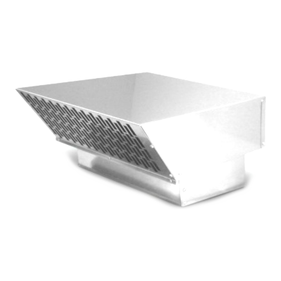
Avvertenze importanti Questo apparecchio è conforme alle pertinenti norme di sicurezza. L’installazione, l’allacciamento alla rete elettrica e le riparazioni devono essere eseguite solo da personale esperto e specializzato altrimenti possono causare pericoli per l’utilizzatore. Per la riparazione e la manutenzione, togliere tensione al motore elettrico. A tal fine staccare il collegamento a spina del cavo elettrico con la cappa aspirante o staccare il cavo di alimentazione della cappa aspirante dalla rete elettrica. - Page 4 Collegare la cappa aspirante con la ventola solo con tubi tondi lisci Ø 150mm ■ utilizzando il minor numero di curve. Se necessario acquistare come accessorio speciale un silenziatore supplementare per tubi da Ø 150 mm. Peso 10 Kg. Con riserva di modifiche costruttive per evoluzione tecnica. Montaggio Montaggio ventola a parete (Fig.
-
Page 5: Allacciamento Elettrico
Allacciamento elettrico Eseguire i collegamento elettrico tramite la spina di alimentazione. Per motivi di sicurezza, la copertura supplementare della spina deve essere sempre collegata e chiusa. Se necessario, sono disponibili come accessorio prolunghe elettriche di lunghezza 5 m. Se si utilizza un cavo di prolunga supplementare, la carcassa della ventola deve essere collegata a terra dall’esterno da un’elettricista specializzato. -
Page 6: Prior To Installation
Important information This appliance conforms to the relevant safety regulations. The installation, the connection to the electrical net and repairs should be carried out only by qualified specialists. Improperly executed repairs can give rise to significant hazards for the user. For repair and care always disconnect the motor from electricity by pulling out the plug from the hood or by disconnecting the hood from the electricity. -
Page 7: Installation
Weight 10 Kg. We reserve the right to construction changes within the context of technical development. Installation Installation of the fan on the wall (Fig.A) 1. Using the template, mark the fixing points on the wall, mark the hole for the air pipe connection and the hole for the electric pipe connection. -
Page 8: Safety Instructions
Safety instructions Regularly check that air can flow freely out of the fan. It is forbidden to obstruct he air outlet grille in a partial way or to cover it with plants. If the connecting cable of the appliance is damaged, the cable must be replaced by the manufacturer or his customer service or a similarly qualified person in order to prevent seriuos injury to the user. -
Page 9: Wichtige Hinweise
Wichtige Hinweise Dieses Gerät entspricht den einschlägigen Sicherheitsbestimmungen. Montage, Anschluss und Reparaturen dürfen nur von Fachkräften durchgeführt werden, ansonsten können Gefährdungen für den Benutzer entstehen. Zur Reparatur und Wartung muss das Gebläse stromlos gemacht werden. Hierzu die Steckverbindung Elektrokabels Dunstabzugshaube trennen, oder Netztanschlussleitung der Dunstabzugshaube vom Stromnetz trennen. -
Page 10: Montage
An den Verbindungsrohren zur Dunstabzugshaube darf keine Reduzierung von Ø 150 ■ mm vorgenommen werden. Einen zusätzliche Schalldämpfer für Rohr150 Ø mm können Sie beim Fachhandel als Sonderzubehör erwerbern. Gewicht 10 Kg. Konstruktionänderungen Im Rahmen der technischen Entwicklung bleiben vorenthalten. Montage Montage an der Wand (Abb. -
Page 11: Elektrischer Anschluss
Elektrischer Anschluss Elektrische Verbindung immer durch Stecker machen. Für Sicherheitsgrunden muss zusätzliche Bedeckung Stecker immer angeschlossen und zu sein. Als Zubehör sind Verlängerungskabel erhältlich mit 5 mt Länge. Wird ein zusätzliches Verlängerungskabel benötigt, muss das Gehäuse durch eine Elektro-fachkraft geerdet sein. Kabel nr. - Page 12 min 10° Entrata/Inlet Ø 150 Uscita/Outlet Uscita/Outlet min 10° Entrata/Inlet Ø 150 Uscita/Outlet Entrata/Inlet Ø 150...
- Page 13 ¨ 8 ¨ 20 ¨ 165...
- Page 14 CAPPA HOOD optional L. 5m...
- Page 17 CAPPA HOOD optional L. 5m...
- Page 18 Non rimuovere le viti! Don’t remove the screws! ¨ 8...
- Page 19 optional L. 5m...
- Page 20 06067714 0114...
Need help?
Do you have a question about the 636 and is the answer not in the manual?
Questions and answers