Advertisement
Quick Links
Advertisement

Summary of Contents for i2o PRV
- Page 1 PRV Control System Installation and Commissioning Manual Author: Imran Jones Issue: Date: 19 Apr 2017 i2O Water Ltd: 4 Benham Road, Southampton Science Park Southampton, SO16 7QJ, United Kingdom www.i2owater.com info@i2owater.com +44 (0) 2380 111 420 Company registration no. 98345 6784...
- Page 2 After installation, calibration and commissioning, the PRV control is adjusted remotely using the i2O Web platform (oNet). The required profiles can be configured in oNet prior to commissioning, and these settings will be applied when the controller first dials-up and connects to the platform.
-
Page 3: Hardware Installation Procedure
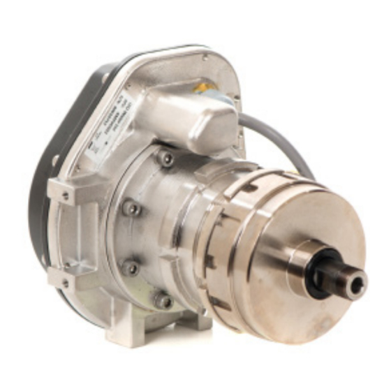
Install APV mounting plate Mount Control Logger and APV to brackets in the orientation shown. Note: APV should be located just above PRV to allow self- bleeding (air) www.i2owater.com info@i2owater.com +44 (0) 2380 111 420 Page 2... - Page 4 Assemble hose connection hardware to the PRV, fitting the T- piece downstream Restriction Block upstream Select and fit the appropriate size of fixed orifice to the Restriction Block, based on the size of the Prepare quick release connectors on 6mm hoses.
- Page 5 Connect 6mm hoses and cables to Control Logger as shown: RED: Upstream pressure (P1) GREEN: Control Space Pressure (Optional) (P3) BLUE: Downstream pressure (P2) A: Flow B: APV (PILOT) C: USB port to connect the Laptop If required, splice flow meter cable in accordance with supplied instructions ...
- Page 6 Connect 12mm hoses to APV and PRV as shown below: 12mm black hoses should: Be as short as possible Have long smooth radius Have no kinks Be routed appropriately to reduce strain Important: Note that the APV shaft moves in and out approximately 10mm in normal operation.
-
Page 7: Calibration Procedure
Calibration procedure Before activating the i2O PRV Control System, the following prerequisites must be met: Verify correct installation of equipment Control Logger set up Flow cable connected Control Logger pre-assigned to a location / associated to a DMA, using the device serial number in i2O Portal Platform ... - Page 8 To consider before start the Calibration Process: All APVs are factory set to provide approx. minimum downstream pressure. Rotating the APV end cap by “1-slot” is equivalent to 1m water pressure in both directions. spanner to adjust the APV where required.
- Page 9 Before proceeding you must make sure that, the APV is isolated from PRV and cannot affect the operational pressures currently set by the PRV. Once in Configurator, Open “APV Calibration”. Select the minimum pressure and downstream start pressure entering values according to what we expect.
- Page 10 For this reason, it is absolutely vital that the controller is left in service mode when the shut-off valves on the PRV are opened, to ensure that the APV is still at the same starting point when it starts to hydraulically control the pressure.
-
Page 11: Commissioning Procedure
Commissioning procedure 1. Ensure the APV is connected to the PRV but with the control space tap either shut. 2. Open the upstream and downstream taps, this will pressurise the i2O APV and pipe work. Check for leaks on both the hoses and the fittings at this point, rectifying or repairing as necessary. -
Page 12: Installation Checklist
Shut off valves installed Control space point available Mount APV rail and Control Logger bracket Mount APV to rail using fittings supplied Fit T-piece to and Restriction block PRV Connect red/blue tubing and cables Connect Flowmeter Connect APV 12mm hoses Record current downstream pressure Pressure: ………….(mH/psi/bar)
Need help?
Do you have a question about the PRV and is the answer not in the manual?
Questions and answers