Advertisement
Quick Links
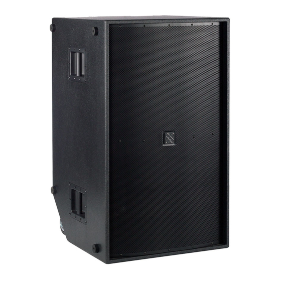
The Crest Audio® Versarray™ Pro 218 Sub Powered Subwoofer speaker system consists of a pair of Peavey® 18" Low Rider® woofers combined with a
super-solid cabinet with a simple, quick, yet flexible rigging system. Designed to provide modular coverage of any size venue, and intended for use
with the companion Versarray™ Pro 112 two-way models, the Versarray™ Pro 218 Sub offers excellent versatility with a very high performance capabili-
ty. The subwoofer system consists of the following woofer components: a pair of Peavey® 18" Low Rider® series woofers with a very long throw 4" voice
coil structure. Capable of over 800W of continuous power handling (AES Std 2-1984) each, these woofers can project a lot of low frequency energy.
The Versarray™ Pro 218 Sub incorporates Peavey's UniVent™ air pumping venting technology. The UniVent™ venting system literally pumps air
through the enclosure, exchanging the stale hot air inside the cabinet for the cooler outside air. This helps keep the woofer operating temperatures
from getting so high, and increases reliability and reduces power compression under heavy continuous drive conditions. The air pumping action is
achieved without excessive turbulence or any significant net asymmetry of total vent air flow.
Power for both woofers is supplied by some very efficient power amplifier systems, controlled by a sophisticated and refined DSP operations system
with Dante connection capability. Total system power is 3000W total peak power, with 1500W total sine wave power for the woofers. This sheer
power is controlled precisely and processed by a high performance DSP system, which provides all the crossover and EQ functions, as well as provid-
ing all limiting, compression and driver protection duties with unfailing attention to every detail of the music.
An optional special groundstack bracket set mounts to the Crest Audio® Versarray 218 Pro Sub, and allows up to three of the Crest Audio® Versarray™
Pro 112's to be mounted on top of the Versarray 218 Pro Sub, and angled upward, for use on stage in a stadium seating situation.
Features
• Dual Woofer Subwoofer SR System
• 3000 Total Peak watts of system power
• 18" Low Rider® 4" VC Peavey® Woofer
• Peavey's UniVent™ air pumping venting technology
• Power amp is fan cooled for maximum reliability
• Full complement of DSP based limiting and compression to protect the drivers from
• Inputs are analog XLR in and/or Dante Ethernet audio network in.
• Analog Output Thru connector is a male XLR
• 18 mm 13 ply Baltic Birch enclosure
• Hammerhead polyurea black finish and black powder-coated cloth lined grilles
• PowerCON TRUE1 TOP Input and Thru AC power connections
• Built-In tilt back casters with 4" wheels
• Optional groundstack bracket set allows up to 3 Crest Audio® Versarray™ 112 Pro 2-Way cabinets to be mounted above the Crest Audio® Versarray™
Pro 218 Sub
Versarray™ Pro 218
Powered Enclosure
Product Specifications
Figure 1 - Frequency Response
Frequency (Hz)
1
overdrive conditions
Advertisement

Summary of Contents for Crest Audio Versarray Pro 218
- Page 1 An optional special groundstack bracket set mounts to the Crest Audio® Versarray 218 Pro Sub, and allows up to three of the Crest Audio® Versarray™...
-
Page 2: Specifications
101 dB SPL (Both speakers driven with 1 watt) Companion Speaker Models Network Group (sold separately): Crest Audio® Versarray™ 112 Pro Primary Ethernet in Maximum Sound Pressure Level Powered Line Array SR System Secondary Ethernet in/out (1 meter): with dual ribbon tweeters, 2-way... - Page 3 Rear Panel Display...
-
Page 4: System Settings Group
Rear Panel Display System Settings Group (1) Volume Buttons These two buttons are used to change the input signal gain from -6 dB to 0 dB in 2 dB increments, controlled by Up and Down buttons. The status LED’s will indicate which gain level is selected. (2) Sensitivity Buttons The module input sensitivity can be changed using these two buttons. -
Page 5: Ac Line Input
Power Group NOTE: The VR112 has an universal power supply, it will work with AC power voltages ranging from 100V to 240VAC at 50/60Hz. Use the proper power cable for your voltage and location. (9) AC OUT/THRU The AC power Out/Thru connector is a Neutrik® powerCON TRUE1 TOP premium quality output connector. Using the supplied 3 foot jumper cable, the power can be daisy-chained to power 1 additional box (100V-120V) and up to 3 additional boxes (220V - 240V). - Page 6 Dante Operation The Dante interface allows digital audio to be used as the input source and can be selected in the VR-Pro Series control application. The transmit and receive routings for all connected Dante devices are set using Dante Con- troller software.
- Page 7 Device Config tab will give you access to settings that can be changed, including the name and sample rate. Note: Crest Audio® can not provide all the necessary information and data to operate and interface Dante® with the Versarray™ Pro 218 system in the Owner’s Manual.
- Page 9 26.275 17.190 26.275 20.400 8.751 2.000 2.000 3.852 5.166 6.501 9.232 42.500 5.906 7.047 2.000 5.674 6.501 8.834 5.166 2.000 .240 2.324 3.875 8.595 REVISION DESCRIPTION ZONE CHK'D...
- Page 10 1.880 6.990 6.990 1.880 1.500 3.852 3.852 5.585 3.500 2.084 26.275 4.000 17.190 2.500 11.000 4.634 1.863 25.000...
- Page 11 2.500 11.000 4.634 1.863 25.000 42.500 PEAVEY CONFIDENTIAL UNLESS OTHERWISE SPECIFIED, POPE DRAWN PEAVEY ELECTRONICS CORP. THE FOLLOWING APPLY: 5022 HARTLEY PEAVEY DRIVE TOLERANCES: 3/13/2019 DATE .XXX = .010 INCHES MERIDIAN, MS 39305 ANGLES = 0.5° CHK'D MATERIAL: DESC. SCALE MECH.
- Page 12 Crest Audio® Versarray™ Pro series - User GUI Use Instructions Installation of the Versarray™ Pro series User GUI Software The software to connect to the Versarray™ Pro 218 Sub speaker system can be found at a link available on the following URL page: https://peaveycommercialaudio.com/versarray...
- Page 13 Using the Versarray™ Pro 218 Sub User GUI Software Once the Versarray™ Pro 218 Sub speaker system cabinets are turned on, connected via Ethernet, and connected to the PC with the Versarray™ Pro series User GUI software installed on it, it is time to start the GUI software.
-
Page 14: Quick Start Instructions
Fig. 2 Quick Start Instructions will follow this segment, and details on all other file management will be available at the end of the descriptions of the GUI parameter pages. Quick Start Instructions A. Once the Ethernet cable is plugged into the PC with the Versarray™ Pro series User GUI software installed on it and running, and the Power turned on to the Versarray™... - Page 15 Each cabinet will come up as you click “Yes”, and click “OK” for as many cabinets as have been networked together. The first time you do this, just click “Yes” and “OK” for one cabinet, so as to look at just one device initially.
- Page 16 Fig. 6 The default first page is the View page, which will allow you to adjust cabinet overall gain and input Sensitivity and other basic parameters. CAUTION! IT IS STRONGLY SUGGESTED THAT BEFORE YOU PROCEED TO ANY OF THE OTHER PARAMETER PAGES, OR CHANGE ANY SETTINGS ON THIS GUI VIEW PAGE, THAT YOU READ AND UNDERSTAND THE DESCRIPTIONS OF EACH PAGE’S FUNCTIONS! WARNING!
- Page 17 definition in those regions. Use of these Bass Boost Presets will add the bass content to the music that needs it, but without risking damage or premature limiting of the Subs or the system as a whole. Trying to add boost in the bass externally to the system will not be as effective or allow for as much additional headroom in terms of maximum peak SPL.
- Page 18 page parameter functions, you can now proceed to make any recommended adjustments or dial in some mild venue EQ or level adjustment on the VR218 Sub using the other pages as listed out below. CAUTION! IT IS STRONGLY SUGGESTED THAT BEFORE YOU PROCEED TO ANY OF THE OTHER PARAMETER PAGES, OR CHANGE ANY SETTINGS ON THIS GUI VIEW PAGE, THAT YOU READ AND UNDERSTAND THE DESCRIPTIONS OF EACH PAGE’S FUNCTIONS! WARNING!
- Page 19 Sixteen characters are available for the file name, so when saving custom presets to the PC software folder outside the Versarray™ Pro 218 Sub, keep that limitation in mind for the file name, and put the important descriptors first in the file name. If a Factory Preset has been customized, then type in your desired name and use that to save the file into DSP memory.
- Page 20 Fig. 10 When clicked on to mute, the loudspeaker block turns red, and mutes the signal flow at that point. Clicking on the block again un-mutes the signal chain at that point. There are also mute controls on the Input Page, and on the Output Page, if the mute is triggered at these locations, the indication still will occur at the View page as well, via a red block icon.
-
Page 21: Auto Standby
Fig. 11 The default menu selection is for assigning the LAN addresses in the line array network. In order for the data to be entered, or any changes to register with the DSP system, you must click on the Apply button, and then the EXIT button. This procedure must be done for each of the Settings choices, or the change or data entered will be lost. - Page 22 This section allows for a firmware update to the DSP operating system, something that will only be done on an infrequent (if ever) basis. Contact Crest Audio/Peavey Electronics for information on whether a firmware update is available or desirable, or check the following URL page: https://peaveycommercialaudio.com/versarray...
- Page 23 transients, e.g., a kick drum mic placed in front of the drum should create a positive pressure wave. Thus the polarity of the Sub should reflect that situation. The polarity button is available for those instances when it is more convenient to take care of a polarity inversion somewhere else in the signal chain, at the speaker system array.
-
Page 24: Input Page
Section 10 DANTE Input Level Local gain control for the DANTE input. Has a range of +/- 12 dB. Factory Setting is -12 dB, so the level can be adjusted as appropriate after establishing DANTE connection. Input Page The Input Page of the Versarray™ Pro 218 Sub DSP GUI provides an overview of controls and parameters of the system, including EQ and compression of the entire signal. - Page 25 Fig. 13 Checkboxes and Radio Buttons provide for various display options from the default view, including the Phase response of both sections. Note that these responses are for the electronics only, and DO NOT represent the actual electro- acoustic output of the system, or of the woofers themselves. Section 12 Noise Gate A noise gate is provided as a means to mute low level noises or sounds from the system.
- Page 26 FIR processing and EQ is not as effective for attempting to correct a Subwoofer’s response, and the latency and number of taps needed to address low frequencies is prohibitive, and thus FIR coefficients are not included in these Sub models. NOTE: It is strongly recommended that the User not try to load or change the FIR coefficients, as they could be loaded in with an error in amplitude or bandwidth, and cause excessive drive level to the system or a particular component, causing damage and/or failure of the system or...
- Page 27 Amplitude changes up to + and – 6 dB, in 0.5 dB increments. Filter Types for each band include: Bell (parametric), with Q ranging from 0.4 to 20 Hi Shelf, with Q ranging from 0.1 to 3.5 Lo Shelf, with Q ranging from 0.1 to 3.5 Low Pass, with Q ranging from 0.1 to 3.5 High Pass, with Q ranging from 0.1 to 3.5 Notch Filter, with Q ranging from 4 to 72...
- Page 28 Range is +/- 12 dB in 0.1 dB increments. This is the same control as Section 9 or 10 on the View Page, depending on which input has been selected at Section 2. See that section for some notes on it’s operation. Section 20 Level Meter, monitors signal level at the point selected by the Meter Select drop down menu.
-
Page 29: Output Page
Output Page The Output Page of the Versarray™ Pro series DSP GUI provides the control of the woofer parameters of the system. See Fig. 14 Fig. 14 Section 24 Frequency and Phase Response Graph and related controls This section provides a graphical display of the frequency response changes dialed in to this Page. Using the Mag and Phase Radio Buttons, you can toggle between the Magnitude ( frequency response) and the Phase of the changes. - Page 30 enhancement of the system. Each band has the following capabilities: Amplitude changes up to + and – 15 dB, in 0.5 dB increments. Filter Types for each band include: Bell (parametric), with Q ranging from 0.4 to 128 Hi Shelf, with Q ranging from 0.1 to 5.1 Lo Shelf, with Q ranging from 0.1 to 5.1 Low Pass, with Q ranging from 0.1 to 5.1 High Pass, with Q ranging from 0.1 to 5.1...
- Page 31 CHANGING THESE SETTINGS FROM THE FACTORY SETTINGS WILL VOID THE WARRANTY! Section 27 Peak Limiter This section provides for adjusting the peak limiting parameters of the woofer, and is used to control the short-term power to the woofer, so it will not be overdriven at high levels. It has an abrupt engagement threshold, no knee, controlled only by the attack and release parameters.
- Page 32 Parameter Adj delay increments are 1 ms (or 0.34 meters), Fine delay increments are approx. 0.0207 ms (or 0.007 meters), with a maximum total delay of 41 ms (or 13.6 meters). Factory setting for this section is 0.0 ms. This setting should be adjusted to match the Versarray™ Pro 218 Sub to the rest of the systems location.
- Page 33 12 dB/Oct. Butterworth 18 dB/Oct. Butterworth 24 dB/Oct. Butterworth 36 dB/Oct. Butterworth 48 dB/Oct. Butterworth 12 dB/Oct. Linkwitz-Riley (LZ) 24 dB/Oct. Linkwitz-Riley 36 dB/Oct. Linkwitz-Riley 48 dB/Oct. Linkwitz-Riley 12 dB/Oct. Bessel (BS) 24 dB/Oct. Bessel Below the Slope/Type Drop down menu bar, is a Frequency (Hz) box, where you can enter the frequency in directly in Hz.
- Page 34 See Rear Panel Display diagram with numbered controls. Fig. 15 shows just the push-button section under review. Fig. 15 We will go over the push buttons one group at a time to show how to use them to configure a line array without the requirement to use a PC and a LAN network to connect to the Versarray™...
- Page 35 This button also gives another 6 dB of level adjustment between cabinets in the same line array, although it would be unlikely that additional attenuation beyond the 6 dB that is available in section C would be needed, these buttons will allow for even more range as needed. Section 3 Polarity A click to choose button allow selection of either Normal (default and indicator blank or white), and...
- Page 36 Fig. 2 Project File Management New Project Starts a new project, prepares the GUI by clearing the Device List of all devices, including ones currently connected to the network. See Fig. 16 Fig. 16 If you click “Yes”, a dialog Window will pop-up, as shown below in Fig. 3. The device ID’s will be different, but the general format will be the same.
- Page 37 Fig. 4 To initiate a Project set-up, click on “Read current settings from Device” to start, then change any parameters you want to alter. You can use the Copy Device function (D1) to copy the changed parameters to the other cabinets in the array as appropriate, make any other changes to any of the other cabinets one at a time in the array (amplitude shading, frequency shading, etc.) or load in of one of the MLAS™...
- Page 38 Fig. 17 Click Yes, as the default Preset “ VR218_Nominal” is also stored in the File folders for future use, as needed. 3. A file manager window will come up with the File Folder contents for the Project files, located at: For Windows 7 and for Windows XP - C:\Program Files (x86)\VR Series v1.2.X\Project For Windows 10 - C:\Program Files\VR Series v1.2.X\Project.
- Page 39 Add Group Contact Crest Audio® for details on this function, or check the Crest Audio® website for more information: https://peaveycommercialaudio.com/versarray Store Program Allows multiple cabinets to have a Preset File stored to memory, see Fig.
- Page 40 the onboard DSP memory location (one through ten of 10 Preset storage slots), and then click on the “Store” button. These cabinets must all be of the same type, i.e., all VR 112’s or all VR 218’s, etc. Recall Program Similar to Storing multiple devices, one can Recall from a list of multiple devices, however, you can only retrieve one Preset file at a time.
- Page 41 Copies the parameters of a highlighted device in the Device List DØ to another device or devices in the Device List. See Fig. 22 NOTE: Do not attempt to copy a VR 218 Preset into a VR 112, copy the Presets from a given model into the same model.
- Page 42 Must use the proper search parameter (IP address) in order for the software to detect devices connected to the network. Preset Files Available for Use Ten On-board Presets 1. VR218_Nominal 2. VR218_BassBoost 3. VR215_Nominal 4. VR215_BassBoost 5. VR218_Nominal 6. VR218_BassBoost 7.
- Page 43 ™ technique at this time, you may find a use for it or it’s files later, or want to experiment with the files in the future. Crest Audio® will provide copies of the Preset files, and any eventual updates of same at the Crest Audio® website at: https://peaveycommercialaudio.com/versarray...
- Page 44 MLAS™ files into a newly created Folder called “Backup”, and then alter the files in the “Preset” folder at will. About the Bass Boost Presets When using the Versarray™ Pro system for use with playback or live DJ, EDM, or other bass heavy music genres, it may be desirable to use the provided Bass Boost Presets.
- Page 45 LOSS OF LAN NETWORK CONNECTION If you experience a loss of the LAN network connection to one or more of the VR speaker systems while operating the Versarray ™ Pro system’s PC DSP GUI software, an error message will be generated.
- Page 46 EQ for the system, as well as limiting and compression to minimize overdrive distortion. The cabinet shall incorporate rigging hardware to interface with the Crest Audio® Versarray™ FlyQWIK™ rigging system, specifically the Crest Audio® Versarray™ VR218 Mk III Ground Stack Kit.
- Page 48 Warranty registration and information for U.S. customers available online at www.peaveycommercialaudio.com/warranty or use the QR tag below Features and speci cations subject to change without notice. Crest Audio 5022 HWY 493 N. Meridian, MS 39305 (601) 483-5365 FAX (601) 486-1278 Logo referenced in Directive 2002/96/EC Annex IV (OJ(L)37/38,13.02.03 and defined in EN 50419: 2005...
Need help?
Do you have a question about the Versarray Pro 218 and is the answer not in the manual?
Questions and answers