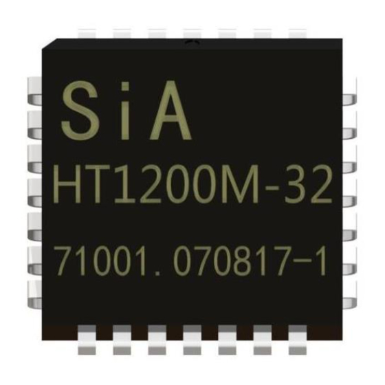
Summary of Contents for Microcyber HT1200M
- Page 1 MICROCYBER HT1200M User Manual HART Modem ASIC (According to HCF_SPEC-54) Version: 1.1 Date: 07.12...
- Page 2 Revision History Version Release Date Detail of Changes 07.12.22 First release...
-
Page 3: Table Of Contents
Characteristics........................... 17 List of Tables Table 1 HT1200M Pin Descriptions..................7 List of Figures Figure 1 HT1200M Hart Modem Typical Application............6 Figure 2 (a) 28Pin PLCC Pinout Package (b) 32Pin LQFP Pinout Package....... 6 Figure 3 Reset Timing......................8 Figure 4 HT1200M Block Diagram..................10 Figure 5 Demodulator Signal Timing.................. -
Page 4: General Description
General Description The HT1200M is a single-chip, CMOS modem for use in Highway Addressable Remote Transducer (HART) field instruments and masters. The modem and a few external passive components provide all of the functions needed to satisfy HART physical layer requirements including modulation, demodulation, receive filtering, carrier detect and transmit-signal shaping. -
Page 5: Typical Application
Typical Application Figure 1 HT1200M Hart Modem Typical Application Pin Assignment Figure 2 (a) 28Pin PLCC Pinout Package (b) 32Pin LQFP Pinout Package HART Modem ASIC | HT1200M | Page Email | fang.siqi@microcyber.cn... -
Page 6: Table 1 Ht1200M Pin Descriptions
UART. TEST11 No connect. — ORXD output Received demodulated HART data to UART. output Carrier detect output. TEST12 No connect. — VSSA ground 12,19 Analog ground — HART Modem ASIC | HT1200M | Page Email | fang.siqi@microcyber.cn... -
Page 7: Pin Description
2200 Hz. When ITXD is high, the modulator output frequency is 1200 Hz. IXTL: Oscillator Input This input to the internal oscillator must be connected to a parallel mode 460.8 kHz HART Modem ASIC | HT1200M | Page Email | fang.siqi@microcyber.cn... - Page 8 This is the power for the digital modem circuitry. VDDA: Analog Supply Voltage This is the power for the analog modem circuitry. VSS: Ground This is the analog and digital ground. HART Modem ASIC | HT1200M | Page Email | fang.siqi@microcyber.cn...
-
Page 9: Function Description
Analog Ground Function Description The HT1200M is a functional equivalent of the SYM20C15 HART Modem. It contains a transmit data modulator and signal shaper, carrier detect circuitry, analog receiver and demodulator circuitry and an oscillator, as shown in Figure 4. -
Page 10: Figure 5 Demodulator Signal Timing
TRANSMIT-SIGNAL SHAPER The transmit-signal shaper generates a HART compliant FSK modulated signal at OTXA. Figure 6 and Figure 7 show the transmit-signal forms of the HT1200M. For IAREF=1.235 V , OTXA will have a voltage swing from approximately 0.25 to 0.75 V... -
Page 11: Figure 7 Otxa Waveform (2200 Hz)
100 mVp-p. Bias Current Resistor The HT1200M requires a bias current resistor to be connected between OCBIAS and Vss. The bias current controls the operating parameters of the internal operational amplifiers and comparators. The value of the bias current resistor is determined by the reference voltage IAREF and the following formula: ⎛... -
Page 12: Figure 8 Receive Schematic
624 Hz and a one-pole, low-pass filter at 2500 Hz. Internally, the HT1200M has a high-pass pole at 35 Hz and a low-pass pole at 90 kHz. The low-pass pole can vary as much as 130 percent. The input impedance of the entire filter is greater than 150 ohm;... -
Page 13: Figure 9 (A) Crystal Oscillator (B) Oscillator
In addition, the HT 1200M consumes less current when an external clock is used. Minimum current consumption occurs with the clock connected to OXTL and IXTL connected to VSS. Figure 9 (a) Crystal Oscillator (b) Oscillator HART Modem ASIC | HT1200M | Page Email | fang.siqi@microcyber.cn... -
Page 14: Package Information
Package Information Figure 10 LQFP32 HART Modem ASIC | HT1200M | Page Email | fang.siqi@microcyber.cn... -
Page 15: Figure 11 Plcc28
Figure 11 PLCC28 HART Modem ASIC | HT1200M | Page Email | fang.siqi@microcyber.cn... -
Page 16: Characteristics
±5 µA IL/IH Output Leakage Current ±5 µA Power Supply Current µA (RBIAS=500kΩ,IAREF=1.235V) IAREF Analog Reference 1.235 ICDREF Carrier Detect Reference 1.15 (IAREF=.08V) OCBIAS Comparator Bias Current µA (RBIAS=500kΩ, IAREF=1.235V) HART Modem ASIC | HT1200M | Page Email | fang.siqi@microcyber.cn... - Page 17 (VDD = 2.7V to 5.5V, VSS = OV, TA = -40 C to +85 C) Parameter Min. Typical Max. Units Demodulater Jitter Conditions % of 1 bit Input frequencies at 1200Hz+/-10Hz,2200Hz+/-20Hz Clock frequency of 460.8kHz+/-0.1% 3.Input(HLXA) asymmetry,0 HART Modem ASIC | HT1200M | Page Email | fang.siqi@microcyber.cn...
- Page 18 (VDD = 2.7V to 5.5V, VSS = OV, TA = -40 C to +85 C) Parameter Min. Typical Max. Units Resonator Tolerance Frequency 460.8 External Clock Frequency 456.2 460.8 465.4 Duty Cycle Amplitude HART Modem ASIC | HT1200M | Page Email | fang.siqi@microcyber.cn...
- Page 19 YOUR FIELDBUS EXPERT CONTACT INFORMATION Address: 17-8 Wensu Street, Hunnan New District, Shenyang, China Website: www.microcyber-fieldbus.com Phone: +86-24-31217278/+86-24-31217280 Fax: +86-24-31217338 Email: fang.siqi@microcyber.cn HART Modem ASIC | HT1200M | Page Email | fang.siqi@microcyber.cn...

Need help?
Do you have a question about the HT1200M and is the answer not in the manual?
Questions and answers