Table of Contents
Advertisement
Available languages
Available languages
Quick Links
Montage- und Betriebsanleitung
Instruction and Assembly Manual
Deutschland:
HENNLICH - HCT GmbH
Im Gewerbegebiet 8
DE-66386 St Ingbert
Tel. +49 6894 95558 - 0
office@hennlich-hct.de
www.hennlich-hct.de
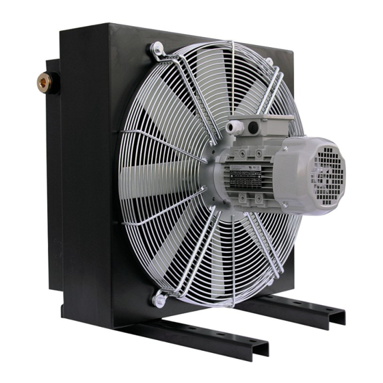
Luftkühler HC
Air Cooler HC
DE
GB
Österreich:
HENNLICH
Cooling - Technologies GmbH
Schnelldorf 51
A-4975 Suben
Tel. +43 7711 / 33066 - 0
cooling@hennlich.at
www.hennlich.at
Schweiz:
HENNLICH (Schweiz) GmbH
Bonnstraße 28
CH-3186 Düdingen
Tel. +41 26 505 14 60
office@hennlich.ch
www.hennlich.ch
Advertisement
Chapters
Table of Contents

Summary of Contents for Hennlich HC Series
- Page 1 Montage- und Betriebsanleitung Instruction and Assembly Manual Luftkühler HC Air Cooler HC Deutschland: Schweiz: Österreich: HENNLICH - HCT GmbH HENNLICH (Schweiz) GmbH HENNLICH Im Gewerbegebiet 8 Bonnstraße 28 Cooling - Technologies GmbH DE-66386 St Ingbert CH-3186 Düdingen Schnelldorf 51 Tel. +49 6894 95558 - 0 Tel.
-
Page 2: Table Of Contents
Montage- und Betriebsanleitung Luftkühler HC Instruction and Assembly Manual Air Cooler HC Inhaltsverzeichnis Übersicht über HC Luftkühler Bauarten 1.1. HCA mit Wechselstrommotor 1.2. HCD mit Gleichstrommotor 1.3. HCH mit Hydraulikantrieb 1.4. HCP mit E-Motor und Pumpe 1.5. HCC Kombikühler Allgemeine Informationen 2.1. - Page 3 Montage- und Betriebsanleitung Luftkühler HC Instruction and Assembly Manual Air Cooler HC Wartung und Reinigung 7.1. Checkliste Wartung 7.2. Wiederkehrende Kontrollen 7.3. Reinigung 7.4. Montage und Demontage der Komponenten Abbildungen 8.1. Anschlüsse: (für Standard-Baureihen) Einbauerklärung im Sinne der Maschinenrichtlinie 2006/42/EG 20_Kühler_Betriebsanleitung_112019-de-eng Seite 3 von 39 Stand: 18.
-
Page 4: Übersicht Über Hc Luftkühler Bauarten
Montage- und Betriebsanleitung Luftkühler HC Instruction and Assembly Manual Air Cooler HC 1. Übersicht über HC Luftkühler Bauarten 1.1. HCA mit Wechselstrommotor (230V / 400V / Sonderspannung) 1.2. HCD mit Gleichstrommotor (12V / 24V) 1.3. HCH mit Hydraulikantrieb (4ccm bis 45ccm) 1.4. -
Page 5: Allgemeine Informationen
HCT behält sich das Recht auf technische Änderungen dieser BA jederzeit vor und kann diese ohne Vorankündigung durchführen. 2.2. Abkürzung HENNLICH Cooling HCT HENNLICH Cooling Technologies GmbH Montage- und Betriebsanleitung 2.3. Verwendungszweck Die Luftkühler von HCT sind grundsätzlich für stationäre Anwendungen konzipiert und dienen vor allem zur effizienten Kühlung von unterschiedlichsten Ölen (Hydraulik, Schmierung,…) und... -
Page 6: Hinweise
Montage- und Betriebsanleitung Luftkühler HC Instruction and Assembly Manual Air Cooler HC von HCT untersagt. Der Kunde haftet hierfür und trägt ebenso die alleinige Verantwortung. Jegliche Gewährleistungsansprüche diesbezüglich sind ausgeschlossen. 2.6. Hinweise Zusätzlich zu dieser allgemeinen Montage und Betriebsanleitung gibt es im Bedarfsfall auch noch weitere Anleitungen zu beachten. -
Page 7: Allgemeine Hinweise
Montage- und Betriebsanleitung Luftkühler HC Instruction and Assembly Manual Air Cooler HC 3.2. Allgemeine Hinweise Gefahr durch elektrische Spannung! Die Elektromotoren der HC-Kühlerbaureihen dürfen ausschließlich von dafür ausgebildetem Fachpersonal (Elektriker) durchgeführt werden. Bei unsachgemäßer Handhabung besteht LEBENSGEFAHR. Die auf den Luftkühler aufgebrachten Warnhinweise sind zu beachten. Vor Wartungsarbeiten an den Luftkühlern, immer darauf achten, das Gerät/System vom Stromnetz zu trennen. -
Page 8: Kennzeichnung
Montage- und Betriebsanleitung Luftkühler HC Instruction and Assembly Manual Air Cooler HC sind dem Typenschild des Motors zu entnehmen. HCP Luftkühler mit Motor Pumpeneinheit Die Luftkühler der Baureihen HCP bestehen grundsätzlich aus einem effizienten Kühlelement, welches mittels Schraubverbindung mit einem Kühlergehäuse verbunden ist. Je nach Ausführung und Baugröße werden Motorkonsolen eingesetzt. -
Page 9: Technische Daten
Montage- und Betriebsanleitung Luftkühler HC Instruction and Assembly Manual Air Cooler HC • „Air cooler“ als Name • Drehrichtung Lüfterrad • Flussrichtung Luftdurchsatz • Kühlerbezeichnung • Artikelnummer • max. zulässiger Betriebsdruck • max. zulässige Betriebstemperatur • Motordaten • Serien Nummer •... -
Page 10: Aufstellung Im Freien
Montage- und Betriebsanleitung Luftkühler HC Instruction and Assembly Manual Air Cooler HC ohne Beeinträchtigung frei zu und abströmen können. Eine erneute Ansaugung der Warmluft (=Thermischer Kurzschluss) muss verhindert werden. Eine ungünstige Aufstellung kann zu erhöhtem Geräuschpegel und reduzierter Kühlleistung führen. Der Einbau muss immer so erfolgen, dass keine Belästigung oder Schädigung an Personen entstehen kann. - Page 11 Montage- und Betriebsanleitung Luftkühler HC Instruction and Assembly Manual Air Cooler HC Fachpersonal durchgeführt werden. Vor dem Anschluss an das Stromnetz sind die Motordaten auf dem Typenschild zu kontrollieren, und es ist sicherzustellen, dass alle elektrischen Anschlussleitungen stromlos sind. Auf etwaige Beschädigungen am Motor oder elektrischen Leitungen ist zu achten.
- Page 12 Montage- und Betriebsanleitung Luftkühler HC Instruction and Assembly Manual Air Cooler HC Anschlußbild Kompakt-Lüftereinheit mit Kabelabgang 3~ 230/400V - 50Hz Kühlertype HCA-xxx.xx-2D-xxx-TSS a) Y-Schaltung (3~ 400V) b) D-Schaltung (3~ 230V) Aderabgänge Kühler: Motorseite Farbcode Aderabgänge Kundenseite Schwarz / Black Grün / Green je nach Schaltungsart D/Y Blau / Blue Weiß...
-
Page 13: Hydraulischer Anschluss
Montage- und Betriebsanleitung Luftkühler HC Instruction and Assembly Manual Air Cooler HC Anschlußbild mit Standard Drehstrommotor Kühlertype HCA-xxx.xx-2/4/6x-xxx-TSS a) Y-Schaltung 3~ „große Spannung“ b) D-Schaltung 3~ „kleine Spannung“ 5.6. Hydraulischer Anschluss Um Beschädigungen am Kühlelement (pmax 26 bar statisch…für alle Größen der CXX.XX) zu vermeiden, ist darauf zu achten, dass das System keine Druckstöße oder Spannungen aufweist. -
Page 14: Inbetriebnahme
Montage- und Betriebsanleitung Luftkühler HC Instruction and Assembly Manual Air Cooler HC Der Eingang des Kühlelementes sollte immer am unteren Anschluss des Kühlelementes gewählt werden, kann aber auch oben erfolgen. Ein diagonal versetzter Ein- und Ausgang wird empfohlen, da andere Anschlüsse zu einer Verschlechterung der Kühlleistung führen können. Die Größe der Anschlüsse hängt von der HC Kühlerbaureihe und Kühlergröße ab. -
Page 15: Im Betrieb
Montage- und Betriebsanleitung Luftkühler HC Instruction and Assembly Manual Air Cooler HC nicht übereinstimmen, überprüfen Sie den korrekten Anschluss und stellen Sie die korrekte Drehrichtung sicher. • Es dürfen keine ungewöhnlichen Geräusche oder Vibrationen auftauchen. Diese deuten auf Beschädigungen des Lüfterrades oder Antriebsmotors (oder anderer Teile) hin. Beschädigte Teile müssen unverzüglich ausgetauscht werden. -
Page 16: Wiederkehrende Kontrollen
Montage- und Betriebsanleitung Luftkühler HC Instruction and Assembly Manual Air Cooler HC Flüssigkeit aus dem Kühlsystem austreten, ist Diese zu ersetzten und das System ist wieder zu entlüften. • Verunreinigung des Kühlelementes Die Luftlamellen müssen sauber und vor Verschmutzung geschützt sein. Verschmutzte Kühlelemente reduzieren die Kühlleistung. -
Page 17: Montage Und Demontage Der Komponenten
Montage- und Betriebsanleitung Luftkühler HC Instruction and Assembly Manual Air Cooler HC Reinigung vom Kühlergehäuse: Für die Reinigung der Kühlergehäuse-Innenseite muss vorher das Kühlelement demontiert werden. Das Gehäuse kann mit Druckluft ausgeblasen, oder mit einem Reinigungsgerät ausgesaugt werden. Um etwaige Verschmutzungen des Motors zu vermeiden, sollte dieser vorher abgedeckt werden. - Page 18 Montage- und Betriebsanleitung Luftkühler HC Instruction and Assembly Manual Air Cooler HC Bei späterer Montage des Lüfters mit der Motorwelle ist die Sicherungsschraube wieder durch eine entsprechende Sicherung (flüssig oder mechanisch) vor einem möglichen Ablösen zu sichern! Vorgehensweise bei der Montage des Kühlernetzes: Kühlernetz anbringen.
-
Page 19: Abbildungen
Montage- und Betriebsanleitung Luftkühler HC Instruction and Assembly Manual Air Cooler HC 8. Abbildungen 8.1. Anschlüsse: (für Standard-Baureihen) (zB. HCD Flex, HCH Flex und HCP Flex ohne Abbildungen) 20_Kühler_Betriebsanleitung_112019-de-eng Seite 19 von 39 Stand: 18. Februar 2020... -
Page 20: Einbauerklärung Im Sinne Der Maschinenrichtlinie 2006/42/Eg
Es handelt sich hier lediglich um Abbildungen zur einfachen Darstellung. Für genaue Abmessungen, Anschlüsse, Dimesionen, etc. sind die jeweiligen Zeichnungen und Datenblätter anzufordern! 9. Einbauerklärung im Sinne der Maschinenrichtlinie 2006/42/EG Hersteller: HENNLICH Cooling-Technologies GmbH Schnelldorf 51 A-4975 Suben, Austria QM-Beauftragter Gerhard Schwarz Produkt: HC Luftkühler... - Page 21 Montage- und Betriebsanleitung Luftkühler HC Instruction and Assembly Manual Air Cooler HC Table of Content Overview of HC Air Cooler Models 1.1. HCA with AC Motor 1.2. HCD with DC Motor 1.3. HCH with Hydraulic Drive 1.4. HCP mit E-Motor und Pumpe 1.5.
- Page 22 Montage- und Betriebsanleitung Luftkühler HC Instruction and Assembly Manual Air Cooler HC 7.1. Checklist Maintenance 7.2. Regular Inspections 7.3. Cleaning 7.4. Assembly and Disassembly of Parts Drawings 8.1. Connection (for standard series) Declaration of Assembly under the terms of Directive 2006/42/EC on Machinery 20_Kühler_Betriebsanleitung_112019-de-eng Seite 22 von 39 Stand: 18.
-
Page 23: Overview Of Hc Air Cooler Models
Montage- und Betriebsanleitung Luftkühler HC Instruction and Assembly Manual Air Cooler HC 1. Overview of HC Air Cooler Models 1.1. HCA with AC Motor (230V / 400V / special voltage) 1.2. HCD with DC Motor (12V / 24V) 1.3. HCH with Hydraulic Drive (4ccm to 45ccm) 1.4. -
Page 24: General Information
Installation and Operating Instructions at any time without prior notice. 2.2. Abbreviations HENNLICH Cooling HCT HENNLICH Cooling Technologies GmbH Montage- und Betriebsanleitung 2.3. Intended use The HCT air cooler is primarily designed to be used in a stationary position for the efficient cooling of oils (hydraulic, lubricating…) and mixtures of glycol and water (at least 20% glycol). -
Page 25: Ammendments
Montage- und Betriebsanleitung Luftkühler HC Instruction and Assembly Manual Air Cooler HC 2.6. Ammendments Additionally to this manual other manuals (for operating and maintenance) have to be noted, if applicable. Particularely: • Manuals for motors/engines • Manuals for pumps • Manuals in case of ATEX requirements •... -
Page 26: General Instructions
4. Product Description 4.1. Design Air coolers in the HC series, (HCA, HCD and HCH), consist of an active cooling element connected by bolts to the cooler cover. Motor cages and brackets are used according to the model and size. Holders and brackets are attached to the cover of the cooler or onto the feet of the cooler to the rest of the cooling unit. -
Page 27: Designation
Montage- und Betriebsanleitung Luftkühler HC Instruction and Assembly Manual Air Cooler HC is connected to the rest of the cooling unit by brackets attached to the cover or the feet of the cooler. The cooler feet are attached to the bottom part of the cooler cover with bolts. The drive motor with the pump is mounted or attached by flanges to the bracket. -
Page 28: Technical Data
Montage- und Betriebsanleitung Luftkühler HC Instruction and Assembly Manual Air Cooler HC marking plate! 4.3. Technical Data The technical data (dimensions, noise level, capacity…) is provided in the relevant data sheets of the HC cooler model series. 5. Installation 5.1. Handling Risk of Crushing! When moving the cooler, care should be taken to secure the cooler and its parts, employing appropriate lifting equipment. -
Page 29: Outdoor Installation
Montage- und Betriebsanleitung Luftkühler HC Instruction and Assembly Manual Air Cooler HC 5.3. Outdoor Installation When using the HC air cooler outdoors, it should be remembered that oil viscosity increases with decreasing temperature. This may lead to a system overload during any cold start of the equipment, resulting in damage to the cooling element. - Page 30 Montage- und Betriebsanleitung Luftkühler HC Instruction and Assembly Manual Air Cooler HC Connection picture axial engine blower unit 230V/50Hz 1~ Cooler type HCA-xxx.xx-2C-xxx-TSS Leg Tails Cooler Engine Site Color Code Leg Tails Customer Site Blau / Blue Braun / Brown Kondensator / Condenser Schwarz / Black N + C...
- Page 31 Montage- und Betriebsanleitung Luftkühler HC Instruction and Assembly Manual Air Cooler HC b) D-control (3~ 230V) Leg Tails Cooler Engine Site Color Code Leg Tails Customer Site Schwarz / Black Grün / Green dep. on control type D/Y Blau / Blue Weiß...
-
Page 32: Hydraulic Line
Montage- und Betriebsanleitung Luftkühler HC Instruction and Assembly Manual Air Cooler HC b) D-control 3~ „small tension“ 5.6. Hydraulic Line To prevent damage to the cooling element (pmax 26 bar static… for standard sizes of CXX.XX), care should be taken to ensure that the system is not subject to any pressure impact or stress. If that is not possible, a separate circuit should be installed for the cooler. -
Page 33: Activation
Montage- und Betriebsanleitung Luftkühler HC Instruction and Assembly Manual Air Cooler HC the connections and fluid leakage, which could be hot. 6. Activation Risk of Injury Prior to activation, check that the HC air cooler is properly installed and connected and that it does not show any signs of damage. -
Page 34: During Operation
Montage- und Betriebsanleitung Luftkühler HC Instruction and Assembly Manual Air Cooler HC 6.2. During Operation The HC air coolers may become extremely hot during operation. Let the device cool down before touching. The maximum permissible temperature (of the oil) must not exceed 120°C. For the HCP-model series the max. -
Page 35: Cleaning
Montage- und Betriebsanleitung Luftkühler HC Instruction and Assembly Manual Air Cooler HC Electric devices must be checked at least once a year by trained qualified staff. HCT recommends daily checks for any signs of damage to the equipment within the remit of inspections. - Page 36 Montage- und Betriebsanleitung Luftkühler HC Instruction and Assembly Manual Air Cooler HC Risk of Burns! The air cooler may become extremely hot during operation and should therefore be allowed to cool down sufficiently prior to handling. Risk of Bruising! To prevent injuries caused by falling parts, or indeed the cooler itself, they should be secured before loosening the bolts.
-
Page 37: Drawings
Montage- und Betriebsanleitung Luftkühler HC Instruction and Assembly Manual Air Cooler HC Main Components: Not shown: 1… Cooler segment 8... Motor console (only if needed) 2… Cooler body / cover 9... Circulating Pump in the HCP Series 3… Feet (Mounted on the Motor) 4…... -
Page 38: Connection (For Standard Series)
Montage- und Betriebsanleitung Luftkühler HC Instruction and Assembly Manual Air Cooler HC 8.1. Other Type Series (e.g. HCD Flex, HCH Flex and HCP Flex are not shown) Connection: (for standard series) These are simplified drawings. Drawings and data sheets for exact dimensions, connections etc. -
Page 39: Declaration Of Assembly Under The Terms Of Directive 2006/42/Ec On Machinery
Montage- und Betriebsanleitung Luftkühler HC Instruction and Assembly Manual Air Cooler HC 9. Declaration of Assembly under the terms of Directive 2006/42/EC on Machinery Manufacturer: HENNLICH Cooling-Technologies GmbH Schnelldorf 51 A-4975 Suben, Austria Designated QM Employee Gerhard Schwarz Product: HC Air Cooler...
Need help?
Do you have a question about the HC Series and is the answer not in the manual?
Questions and answers