Table of Contents
Advertisement
Advertisement
Table of Contents

Related Manuals for Burdick Atria 3000


Summary of Contents for Burdick Atria 3000
- Page 1 Service Manual Atria™ 3000 Electrocardiograph Part No. 070-1133-00 Rev. A...
- Page 2 However, we can not guarantee against the deterioration of com- ponents due to aging and normal wear. CAUTION — The Atria 3000 ECG is a restricted device. Federal law restricts the sale, distribution, or use of this device to, by, or on the lawful order of a health professional.
-
Page 3: Table Of Contents
Table of Contents Warnings & Cautions ......... . iii Definitions of Symbols Used . - Page 4 Power Supply Board and Power Supply Cover ....4-6 Optional I/O Board and I/O Board Cover ..... . . 4-7 Front End Digital Board .
-
Page 5: Warnings & Cautions
Warnings & Cautions Warnings WARNING: There can be high voltage near the fuse, AC inlet and transformer. Always unplug the electrocardiograph before taking it apart. Cautions CAUTION: Always turn the electrocardiograph off and disconnect the power cord before cleaning. Do not pour liquids (such as alcohol or other cleaners) on the unit. - Page 6 Service Manual Atria...
-
Page 7: Definitions Of Symbols Used
Definitions of Symbols Used Attention. Consult accompanying documents. Danger! High voltage. Hazardous voltage. Defibrillation-Protected Type CF Equipment. Equipotentiality (used to label the grounding lug). Alternating Current (AC). Direct Current (DC). Automatic Operation. Manual Operation. On/Standby. Stop Function. Modem port. Ethernet port. USB port. - Page 8 Certified for both the U.S. and Canadian markets, to the applicable U.S. and Canadian safety standards. Component is certified for both the U.S. and Canadian markets, to the applicable U.S. and Canadian safety standards. Device or component is certified for the Japanese and/or Asian markets. Service Manual Atria...
-
Page 9: General Information
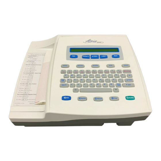
Chapter General Information About the Atria Electrocardiographs The Atria ECG is a multichannel non-interpretive/interpretive electrocardiograph. You operate the electrocardiograph by pressing various keys on the keypad. A thermal printer makes hard copy printouts of text and waveforms for permanent records. The servicing of the Atria electrocardiograph is similar regardless of which model you have. -
Page 10: Basic System Block Diagram
Chapter 1 General Information Basic System Block Diagram Atria 3000 Power Supply/Printer Board Battery Equipotential Isolation Paper Printer AC Power Power In Supply (Brick) KeyBoard Patient Cable Atria Main Board (Front end and Host processor) Upgrade Software Compact Upgrades Flash... -
Page 11: Technical Specifications
216 mm thermal dot array Paper dimension 8.5" x 11" (US letter) 210mm x 300mm (A4) Paper type ® Thermal sensitive (Burdick Assurance Heartline™ paper recommended) Chart speeds 10, 25, 50 mm/sec Gain 5, 10, 20 mm/mV Chest or Limb (may be split) Printout formats 3, 4, 6 or 12 channels;... - Page 12 Chapter 1 General Information Environmental: Operating temperature 50°F to 104°F (10°C to 40°C) Operating relative humidity 10% to 95% non-condensing Operating atmospheric pressure 1060 hPa to 700 hPa (-500 ft to 10,000 ft reference to sea level) Storage temperature -4°F to 131°F (-20°C to 55°C) Storage relative humidity 25% to 95% non-condensing Storage atmospheric pressure...
-
Page 13: Service & Maintenance
Chapter Service & Maintenance What You Will Need You will need only standard electronics tools to perform any testing or repairs. Test equipment must be in good condition and calibrated regularly. You will need: ✔ Digital Multimeter ✔ Leakage Current Meter/Safety Analyzer ✔... -
Page 14: Visual Inspection
Chapter 2 Service & Maintenance Visual Inspection Check for anything out of the ordinary. Are there any cracks or missing parts? Are the cords and connectors damaged or weak? Does the electrocardiograph seem to operate properly? If everything looks fine, but you still suspect a problem, check inside the electrocardiograph for loose connections, burn damage or contamination from liquids. -
Page 15: Printhead
Service Function Menus and Options Printhead Keep the thermal array printhead free of dirt and other foreign materials. WARNING: The printhead is very sensitive to static electricity. Use an antistatic work surface. Light printing (particularly at the baseline) may be an indication that the printhead is dirty. -
Page 16: Hidden Menu
Keyboard Test This function allows you to test the keyboard for proper functioning. Press any key on the keyboard and verify that the display shows the key selected. This test is used by Burdick manufacturing. Atria Service Manual... -
Page 17: Special Functions Menu
The last option in the . Use the Special Functions menu to view, enable or disable features. NOTE: There may be other functions in addition to those described below. They are included for Burdick Inc. Engineering use only. Atria Service Manual... - Page 18 Chapter 2 Service & Maintenance Hidden Menu From the Special Functions 1. Press to scroll to 2. Press 3. Type Continue with step 4 below; or, to enable a feature, continue with step 4 on page 2-7. To view or disable features: 4.
-
Page 19: Measuring Chassis Leakage Current
Measuring Chassis Leakage Current Or, to enable features: 4. Enter the password and press NOTE: Contact Burdick Technical Support Department for the password, once the feature has been ordered. 5. Press to select the listed feature. 6. Press to scroll to the ON option. -
Page 20: Measuring Patient Leakage Current
Chapter 2 Service & Maintenance Measuring Patient Leakage Current Use a high quality meter or safety analyzer capable of testing to AAMI specifications. An inappropriate meter can produce erroneous leakage readings. Do the tests at a nonconductive work station. Be careful! The meter must be suitably insulated and capable of withstanding the power line voltage. -
Page 21: Problem Solving
Chapter Problem Solving Troubleshooting Past experience shows that most service calls are due to poor ECG technique or broken cables. Before you take apart the electrocardiograph, make sure that these things are not causing the problem. Make use of the Operating Instructions manual. - Page 22 - defective or poorly seated - reseat or replace queue sensor queue sensor Printing is too light or too - use of non-approved paper - replace with Burdick paper dark - paper setting does not match - configure Paper Type (in paper...
- Page 23 Troubleshooting Symptom: Possible cause: Procedure: No keypad response - defective or poorly seated - reseat cable or replace keypad keypad cable - defective keypad - replace keypad - defective front end digital - replace front end digital board board - oil from hand lotions has - clean the underside of the permeated the keypad and keypad and the top side of...
-
Page 24: Connector Pinouts
Chapter 3 Problem Solving Connector Pinouts You can use the following tables to help locate signals during troubleshooting. Power In The power connector uses a 6-pin 0.1” center MTA style header. DC in + 24V DC in - 0V SAFETY GROUND NC/POLARIZER SAFETY GROUND SAFETY GROUND... -
Page 25: Battery
Connector Pinouts Battery The battery uses a 4-conductor card edge connector. BAT POSITIVE BAT POSITIVE BAT NEGATIVE BAT NEGATIVE Atria Service Manual... - Page 26 Chapter 3 Problem Solving Atria Service Manual...
-
Page 27: Component Replacement
Chapter Component Replacement This section contains instructions for removing and replacing the Atria electrocardiograph’s major subassemblies. To find an assembly, refer to “Parts Lists & Exploded Views” on pg. 4-9. WARNING: There can be high voltage near the power brick AC inlet. -
Page 28: Battery
Chapter 4 Component Replacement Battery WARNING: Never remove the battery pack and attempt to recharge it using an external battery charger. Fire or explosion may result. WARNING: Verify that external power is disconnected before removing or replacing battery. A blank display is not a reliable indication of disconnected external power. -
Page 29: Top Enclosure
Top Enclosure Top Enclosure 1. Unplug the electrocardiograph. 2. Disconnect the battery as described earlier. 3. Turn the electrocardiograph over and remove the two (2) screws from the bottom of the electrocardiograph (screws are located on left side of bottom enclosure). 4. -
Page 30: Paper Drive Assembly
Chapter 4 Component Replacement Paper Drive Assembly NOTE: The paper drive assembly is replaced as a unit. Do not disassemble. CAUTION: The printhead is very sensitive to static electricity. Use an antistatic work surface. 1. Unplug the electrocardiograph and disconnect the battery as described earlier. -
Page 31: Queue Sensor
Queue Sensor Queue Sensor CAUTION: The queue sensor is very sensitive to static electricity. Use an antistatic work surface. 1. Remove the top enclosure as described earlier. 2. Disconnect queue sensor from paper drive assembly. 3. Remove plastic screw and nut from paper drive assembly. 4. -
Page 32: Power Supply Board And Power Supply Cover
Chapter 4 Component Replacement Power Supply Board and Power Supply Cover WARNING: There can be high voltage near the fuse, AC inlet and transformer. Always unplug the electrocardiograph before taking it apart. CAUTION: The power supply board is very sensitive to static electricity. -
Page 33: Optional I/O Board And I/O Board Cover
Optional I/O Board and I/O Board Cover Optional I/O Board and I/O Board Cover CAUTION: The optional I/O board is very sensitive to static electricity. Use an antistatic work surface. 1. Unplug the electrocardiograph. 2. Disconnect the battery as described earlier. 3. -
Page 34: Front End Digital Board
Chapter 4 Component Replacement Front End Digital Board CAUTION: The front end digital board is very sensitive to static electricity. Use an antistatic work surface. 1. Remove the top enclosure as described earlier. 2. Remove the paper drive assembly as described earlier. 3. -
Page 35: Parts Lists & Exploded Views
Parts Lists & Exploded Views Parts Lists & Exploded Views To locate components, refer to the figure on page 4-10 and this parts list: Item # Part # Quantity Description 650-1421-00 Top Enclosure Assembly, Service 215-0223-00 Screw 650-1414-00 Paper Door Assembly, Service 650-1464-00 Battery Cover Assembly, Service 146-0126-00... - Page 36 Chapter 4 Component Replacement Figure 1 - Atria Exploded View 4-10 Atria Service Manual...
-
Page 37: Index
Index battery saver mode paper drive assembly, replacement battery, replacement parts list block diagram patient leakage current power down timer See battery saver mode power supply board, replacement cable maintenance preventive maintenance cautions printer test alternate sequence chassis leakage current printer test sequence cleaning printhead maintenance...
Need help?
Do you have a question about the Atria 3000 and is the answer not in the manual?
Questions and answers