Table of Contents
Advertisement
Quick Links
• This manual is integrant and essential to the product. Carefully read the instructions contained herein
as they provide important hints for use and maintenance safety.
• This device is to be used only for the purposes it has been designed to. Other uses should be
considered improper and dangerous. The manufacturer is not responsible for possible damages caused
by improper, erroneous and irrational uses.
• Elettronica Santerno is responsible for the device in its original setting.
• Any changes to the structure or operating cycle of the device must be performed or authorized by
Elettronica Santerno.
• Elettronica Santerno assumes no responsibility for the consequences resulting by the use of non-
original spare-parts.
• Elettronica Santerno reserves the right to make any technical changes to this manual and to the
device without prior notice. If printing errors or similar are detected, the corrections will be included in
the new releases of the manual.
• The information contained herein is the property of Elettronica Santerno and cannot be reproduced.
Elettronica Santerno enforces its rights on the drawings and catalogues according to the law.
SINUS PENTA
PENTA MARINE
IRIS BLUE
SAFE TORQUE OFF
FUNCTION
- Application Manual -
Issued on 04/03/2015
R.00
Elettronica Santerno S.p.A.
Via della Concia, 7 - 40023 Castel Guelfo (BO) Italia
Tel. +39 0542 489711 - Fax +39 0542 489722
santerno.com
• 15W0102B300 •
info@santerno.com
E n g l i s h
Advertisement
Table of Contents

Related Manuals for Elettronica Santerno SINUS PENTA

Summary of Contents for Elettronica Santerno SINUS PENTA
- Page 1 • Elettronica Santerno assumes no responsibility for the consequences resulting by the use of non- original spare-parts. • Elettronica Santerno reserves the right to make any technical changes to this manual and to the device without prior notice. If printing errors or similar are detected, the corrections will be included in the new releases of the manual.
-
Page 2: Table Of Contents
STO FUNCTION SINUS PENTA APPLICATION MANUAL PENTA MARINE IRIS BLUE TABLE OF CONTENTS 1. BASICS ........................4 1.1. GENERAL ........................ 4 1.2. SCOPE AND APPLICATION ..................8 2. ES927 CONTROL BOARD ..................12 3. DEFINITION OF THE SYSTEM ................14 3.1. - Page 3 Index of Figures Figure 1 – Some Sinus Penta compact models .................... 5 Figure 2 – Installation example of a Sinus Penta S64/S70 ................6 Figure 3 – Installation example of a Sinus Penta S74................... 7 Figure 4 – Installation example of a Sinus Penta S75/S80 ................7 Figure 5 - Example schematic diagram of STO function with Safety Relay PILZ PNOZ X3 for safe power cut off ................................
-
Page 4: Basics
The STO function can be used also to prevent unexpected start up of the motor. The STO function in the Sinus Penta, Penta Marine and Iris Blue drives is obtained at a hardware level and its activation is absolutely independent of the software and the CPU of the inverter. The drive firmware implements only non-critical diagnostic functions related to the STO function. -
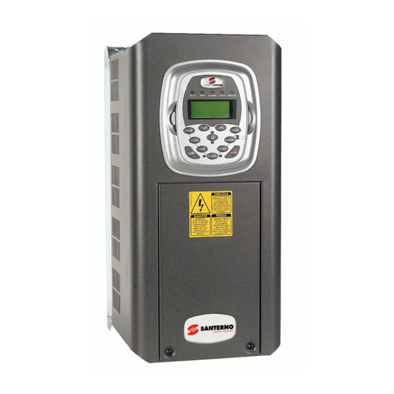
Page 5: Figure 1 - Some Sinus Penta Compact Models
Figure 1 (compact inverter) and Figure 2, Figure 3, Figure 4 (modular inverter) show the different sizes and structures of inverters relative to the Sinus Penta drives. The Penta Marine and Iris Blue product lines share the same sizes and physical appearance as the Sinus Penta;... -
Page 6: Figure 2 - Installation Example Of A Sinus Penta S64/S70
STO FUNCTION SINUS PENTA APPLICATION MANUAL PENTA MARINE IRIS BLUE Figure 2 – Installation example of a Sinus Penta S64/S70 6/27... -
Page 7: Figure 3 - Installation Example Of A Sinus Penta S74
STO FUNCTION SINUS PENTA APPLICATION MANUAL PENTA MARINE IRIS BLUE Figure 3 – Installation example of a Sinus Penta S74 Figure 4 – Installation example of a Sinus Penta S75/S80 (S75 includes two power supply unit modules) 7/27... -
Page 8: Scope And Application
STO FUNCTION SINUS PENTA APPLICATION MANUAL PENTA MARINE IRIS BLUE 1.2. Scope and Application The drives support the Safe Torque Off (STO) function according to standards EN 61800-5-2:2007, EN ISO 13849-1:2008, EN 61508:2010. The STO may be used where power cut off is required to prevent unexpected start up. The STO function disables the control voltage of the power semiconductors of the drive output stage, thus preventing the inverter from generating the voltage required to rotate the motor (see diagram below). -
Page 9: Figure 5 - Example Schematic Diagram Of Sto Function With Safety Relay Pilz Pnoz X3 For Safe Power Cut Off
STO FUNCTION SINUS PENTA APPLICATION MANUAL PENTA MARINE IRIS BLUE Figure 5 - Example schematic diagram of STO function with Safety Relay PILZ PNOZ X3 for safe power cut off The circuit operation is described below. Start/Stop command is obtained through special-purpose push-buttons. -
Page 10: Figure 6 - Example Schematic Diagram Of The Sto Function With Simple Emergency Pushbutton
STO FUNCTION SINUS PENTA APPLICATION MANUAL PENTA MARINE IRIS BLUE Figure 6 - Example schematic diagram of the STO function with simple emergency pushbutton 10/27... - Page 11 STO FUNCTION SINUS PENTA APPLICATION MANUAL PENTA MARINE IRIS BLUE The circuit operation is straightforward, and similar to the previous example. In both cases, the ENABLE-A and ENABLE-B command circuits shall be carried out with care on the cables layout, avoiding that possible damage to cable insulation could result in unwanted circuit excitation.
-
Page 12: Es927 Control Board
STO FUNCTION SINUS PENTA APPLICATION MANUAL PENTA MARINE IRIS BLUE 2. ES927 CONTROL BOARD LEDs and Display M9 Pin 1-Label S ENABLE-B M4 Pin 2-Label 15 ENABLE-A Figure 7 – Top view of ES927 12/27... -
Page 13: Figure 8 - Front View Of Terminal Blocks For Es927
STO FUNCTION SINUS PENTA APPLICATION MANUAL PENTA MARINE IRIS BLUE M9 Pin 1-Label S ENABLE-B M4 Pin 2-Label 15 ENABLE-A Figure 8 – Front view of terminal blocks for ES927 LED L1 RUN LED L2 LED L4 15V PWM ENABLE LED L5 15V... -
Page 14: Definition Of The System
APPLICATION MANUAL PENTA MARINE IRIS BLUE All the Sinus Penta, Penta Marine and Iris Blue drives are equipped with the same ES927 control board. Figure 7, Figure 8 and Figure 9 show the relevant components related to the STO function. - Page 15 STO FUNCTION SINUS PENTA APPLICATION MANUAL PENTA MARINE IRIS BLUE The STO function breaks out the PWM logic signals at ES927 control board level; therefore, it is completely independent of the power size of the drive. 15/27...
-
Page 16: Diagnostics
STO FUNCTION SINUS PENTA APPLICATION MANUAL PENTA MARINE IRIS BLUE 4. DIAGNOSTICS The STO function is based on a double channel with diagnostic (1oo2 in the IEC 61508-6 nomenclature) hardware architecture. This means that diagnostic tests are required to validate the STO function and to periodically verify the hardware integrity. - Page 17 STO FUNCTION SINUS PENTA APPLICATION MANUAL PENTA MARINE IRIS BLUE The DT01 proof-test needs to be performed in 4 steps: Step nr1 Drive is working with motor torque applied to motor. This condition is obtained by energizing both STO input signals (ENABLE-A and ENABLE-B) and transmission of PWM commands from Microcontroller to the IGBT Drivers.
- Page 18 STO FUNCTION SINUS PENTA APPLICATION MANUAL PENTA MARINE IRIS BLUE DT02 Periodic Proof-test (Diagnostic LED “PWM Enable” L2) Based on hardware components and firmware code. Performed with a specified sequence of 4 steps. Checked by visual inspection of Diagnostic LED “PWM Enable” L2.
- Page 19 STO FUNCTION SINUS PENTA APPLICATION MANUAL PENTA MARINE IRIS BLUE The proof-test is to be performed in 4 steps: Step nr1 Drive is working with motor torque applied to motor. This condition is obtained by energizing both STO input signals (ENABLE-A and ENABLE-B) and by the transmission of PWM commands from Microcontroller to the IGBT Drivers.
-
Page 20: Validating The Operation Of A Safety Function
STO FUNCTION SINUS PENTA APPLICATION MANUAL PENTA MARINE IRIS BLUE 5. VALIDATING THE OPERATION OF A SAFETY FUNCTION Safety Standards EN IEC 62061 and EN ISO 13849 require that the final assembler of the machine validates the operation of the safety function with an acceptance test. - Page 21 In case of ES927 damaged board, the decommissioning of the board and the replacement with a new one is MANDATORY: restart the safety function. Any damaged ES927 board must be sent to the Customer Service of Elettronica Santerno S.p.A. for analysis and disposal. If any safety function failures are detected, including STO, please contact Elettronica Santerno S.p.A. ...
-
Page 22: Commissioning, Maintenance And Decommissioning, Disposal, Fault Tracing And Diagnostics
‘STO Acceptance Tests’. The Mean Time to Repair is assumed equivalent to 8 hours. The damaged ES927 board needs to be sent to the Customer Service of Elettronica Santerno S.p.A. for analysis and disposal. -
Page 23: Alarm Messages Generated By The Drive
STO FUNCTION SINUS PENTA APPLICATION MANUAL PENTA MARINE IRIS BLUE 6.5. Alarm Messages Generated by the Drive Fault Cause What to do User could try to reset the alarm. In case of persistent alarm, board ES927 is damaged A140 Internal hardware “Torque Off not... -
Page 24: Components For Sto Applications
7.1.1. Environmental Requirements for Equipment Installation, Storage and Transport Any electronic board installed in the inverters manufactured by Elettronica Santerno is tropicalized. This enhances electrical insulation between the tracks having different voltage ratings and ensures longer life of the components. It is however recommended that the requirements below be met: –10°C to +55°C... -
Page 25: Safety Relay Proposal For Sto Application
STO FUNCTION SINUS PENTA APPLICATION MANUAL PENTA MARINE IRIS BLUE 7.2. Safety Relay Proposal for STO Application General requirements IEC 61508 and/or EN/ISO 13849-1 Type Safety relay Manufacturer PILZ – Part Number PNOZ X3. 10P Example Approvals SILCL 3 according to EN 62061 and PL according to EN ISO 13849-1 7.3. -
Page 26: Sto Technical Data
8.1. STO Data Related to Safety Standards Data related to safety standards IEC 61508, EN 61800-5-2, EN/ISO 13849-1 are listed below. Data apply to all sizes of inverter of Sinus Penta, Iris Blue and Penta Marine line. IEC 61508 EN/ISO 13849 Category 2.383 x 10... -
Page 27: Terms And Abbreviations
STO FUNCTION SINUS PENTA APPLICATION MANUAL PENTA MARINE IRIS BLUE 9. TERMS AND ABBREVIATIONS ccording to EN 61508-6, Table B.1: Abbreviation Term (units) Proof-test interval (hour) Mean time to restoration (hour) MTTR Diagnostic coverage (expressed as a fraction in equation and as a percentage elsewhere) ...
Need help?
Do you have a question about the SINUS PENTA and is the answer not in the manual?
Questions and answers