Table of Contents

Summary of Contents for IDTECH SmartPIN K100 3.X
- Page 1 SmartPIN K100 3.X Technical Reference Manual 80114510-001-D July 3, 2019 International Technologies & Systems Corporation 10721 Walker Street, Cypress, CA 90630-4720; Tel: (714) 761-6368; Fax: (714) 761-8880 www.idtechproducts.com...
- Page 2 Revision History Rev. Date Description of Changes 4/19/2016 Release to Revision A 6/8/2016 New engineering drawings. Miscellaneous edits. Include USB VID & PID. Expanded explanation of Get Numeric Entry. 6/17/2016 Include tamper-protection info (Sections 3.10, 6.4, 6.5). 6/22/2016 Added USB descriptor info. 11/30/2016 Removed "sleep mode."...
- Page 3 ID TECH 10721 Walker Street, Cypress, CA90630 Voice: (714) 761-6368 Fax: (714) 761-8880 Copyright 2017 by ID Technologies, Inc. All rights reserved. The information contained herein is provided to the user as a convenience. While every effort has been made to ensure accuracy, ID TECH is not responsible for damages that might occur because of errors or omissions, including any loss of profit or other commercial damage, nor for any infringements or patents or other rights of third parties that may result from this information’s use.
-
Page 4: Table Of Contents
Table of Contents INTRODUCTION ..............................6 FEATURES ................................6 PHYSICAL SPECIFICATION ............................. 7 HYSICAL PECIFICATION ....................................PERATING NVIRONMENT ................................... LECTRICAL........................................UTPUT ONNECTIONS ....................................UDIO EEDBACK ......................................ATTERY .......................................... LED ................................. 9 PERATION ELIABILITY........................................ERIPHERAL EVICE AIRING ..................................3.10 AMPER ROTECTION EATURES ................................ - Page 5 OTE ..........................................ATE ......................................ATE ......................................ARITY ........................................ARITY ........................................ITS ....................................... ITS ....................................... ERROR CODES ..............................22 NOTES ..................................23 Copyright © 2019, International Technologies & Systems Corp. All rights reserved. Page 5 of 24...
-
Page 6: Introduction
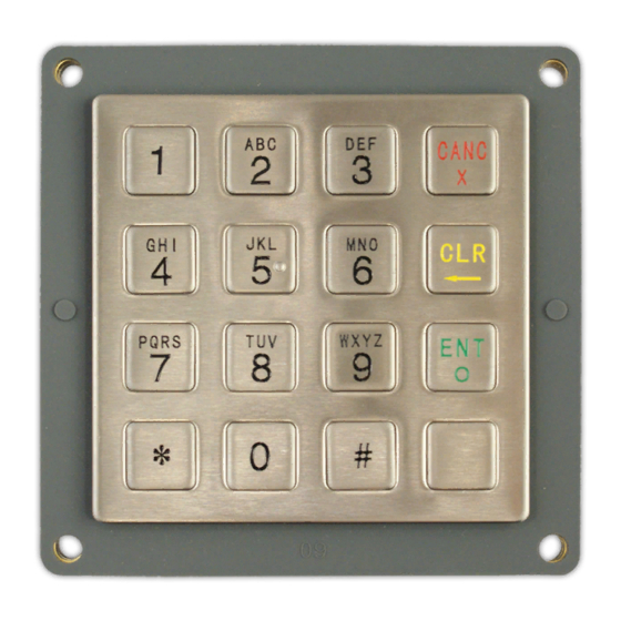
Introduction ID TECH’s SmartPIN K100 3.X is a PCI 3.X certified, ruggedized PIN-entry device designed for use in vending and ATM environments. The 4x4, 16-key layout is a familiar format seen on other unattended payment devices and is specifically designed to meet applicable ADA, ANSI, and ISO standards. -
Page 7: Physical Specification
Physical Specification Physical Specification Materials & Finish Keys: Material: Stainless steel with brushed finish Key Embossing (ADA compliant) tactile symbol Numeric keys, 12 each, includes * and # (or ↓ and ↑) Operation Keys (4 each) Key graphics are etched or engraved The operation keys (CANC, CLR, ENT) have engraved color bars near the bottom of the key surface The operation keys also have raised symbols (X, <... -
Page 8: Electrical
Electrical Power is supplied to the unit in the following manner: RS232 interface – uses A/C power adapter, 5VDC +/- 10% USB interface – Hub/PC supplied power Operation current: <100mA Output Connections The RS-232 Output complies with the standard RS-232 Pin-out as listed below: Pin number RS-232 Audio Feedback... -
Page 9: Operation Led
Operation LED The Op-LED is a surface mount, tri-color LED, which is visible from the back of the housing (using a light pipe). It is molded into the housing. The LED provides operating information for the PIN Pad. The following chart gives operation status meanings. The blink rate is about 12 times per minute with an LED-on period of about 2.5 second. -
Page 10: Usb Descriptors
USB Descriptors USB Descriptor Info The USB version of the K100 can be operated in USB-HID mode. When the K100 is operated in HID mode, it behaves like a vendor-defined USB-HID device. A direct communication path can be established between the host application and the reader without interference from other HID devices. -
Page 11: Interface Descriptor
4.1.3 Interface Descriptor Field Value Description Length Des type Interface No. Alternator Setting # EP Interface Class Sub Class Interface Protocol iInterface 4.1.4 HID Descriptor Field Value Description Length Des type bcdHID 00 01 Control Code numDescriptors Number of Class Descriptors to follow DescriptorType Report Descriptor Descriptor Length... -
Page 12: Report Descriptor
4.1.7 Report Descriptor Value Description 05 02 Usage Page (Simulation Controls) 09 26 Usage (Driving Control) A1 01 Collection (Application) 05 0C Usage Page (Consumer Devices) 15 00 Logical Minimum 26 FF 00 Logical Maximum 75 08 Report Size 95 40 Report Count 81 03 Input... -
Page 13: Get Numeric Entry
3. Get Encrypted PIN with DUKPT Key under Triple DES or Single DES mode using Encrypted PAN: Command Body is 75 46 07 11 & 24bytes data (Encrypted PAN) Response Body: 06 + 20 ASCII code KSN + 24 ASCII code Encrypted PIN block 4. -
Page 14: Get Function Key
020b000630313233343536373839071303 The data (shown above in boldface) contains ASCII 0x30 through 0x39. Get Function Key Command Body is 75 46 0B Wait 3 Minutes While you press Back key, SmartPIN K100 Sends "B" While you press Cancel key, SmartPIN K100 Sends "C" While you press Enter key, SmartPIN K100 Sends "E"... -
Page 15: Get Model Number
<Fre1> <Fre2> is the first and second nibble for the first byte of frequency. <Fre3> <Fre4> is the first and second nibble for the second byte of frequency. If the frequency is 1000Hz (0x03E8), <Fre1> <Fre2> <Fre3> <Fre4> will be 0x45 0x38 0x30 0x33. <Dur1>... -
Page 16: Get Real Time
0x0C RKI-KEK DUKPT Key 0x0C RKI-KEK DUKPT Key 0x08 PIN Master Key 0x08 PIN Master Key 0x0D Pairing BDK 0x0D Pairing BDK Key(PINPAD) Key(PINPAD) Get Real Time Command Body is 75 46 51 Response Body is 06 + Year/Month/Date Hour:Minute:Second 6.10 Get all Fix/Removal Records Command Body is 75 46 52... -
Page 17: General Task Commands
General Task Commands Restart Command Command Body is 78 46 49 Response Body is 06 Get Firmware Version Command Body is 78 46 01 – Get Release Version Response Body is 06 & some bytes ASCII codes Enter into Bootloader Command Body is 78 46 7A 49 52 46 57 00 00 00 00 00 00 00 00 Response Body is 06 - Device has the function, Or... -
Page 18: Activate Removal Of Device (Legally, Via Password)
The process is: Step2.1 Press Default Loading Key Password once and device will beep Complete Tone. (If the first numeric key is pressed, Device will stop Always beeps). Step2.2 Press New Password first times, and device will beep Complete Tone. (New Password need not be same as Default Loading Key Password.) ... - Page 19 Device enters into “Want Fix / Removal Device State”. Device beeps always, the User need modify passwords. Please do Step2 If there are two User Activation Passwords in device. Device beeps Normal Tone and enters into “Want Fix / Removal Device State”. ...
-
Page 20: Rs232 Task Commands
RS232 Task Commands Note 1. If the device is connected with RS232 Cable, the settings will be saved in system and be valid after it response ACK to host. 2. If the device is connected with USB Cable, the settings only be saved in system and be valid when the device is connect with RS232 Cable. -
Page 21: Get Stopbits
StopBits ASCIIChar Response Body is 06 Get StopBits Command Body is 70 52 01 45 Response Body is 06 70 45 01 ASCIIChar Copyright © 2019, International Technologies & Systems Corp. All rights reserved. Page 21 of 24... -
Page 22: Error Codes
Error Codes Error Code Definition 0x0100 Log (Removal / Fix) is full Key Type (DES/TDES) of Session Key is not same as the related Master 0x0300 0x0400 Related Key was not loaded 0x0401 Related Key was not loaded 0x0500 Key Same 0x0700 No BDK of Pairing MSR Key Have BDK of Pairing MSR Key, Not Pairing with MSR (No PAN... -
Page 23: Notes
0x550F Other Error 0x6000 Save or Config Failed / Or Read Config Error 0x6200 No Serial Number 0x6900 Invalid Command - Protocol is right, but task ID is invalid Unsupported Command - Protocol and task ID are right, but command is 0x6A00 invalid Unknown parameter in command - Protocol task ID and command are right,... - Page 24 If Base Time was loaded, while receiving Load Base Time Command, Response Body is 15 0E If have not related Master Key after send “Load Session Key”, Response Body is 15 04 00 If have not DUKPT Key after send "Get Encrypted PIN with DUKPT Key", Response Body is 15 04 00 ...
Need help?
Do you have a question about the SmartPIN K100 3.X and is the answer not in the manual?
Questions and answers