
Summary of Contents for Guralp Systems 3T Emergency Mass-Locking
- Page 1 3T Emergency Mass-Locking Technical Procedure Document No: PRC-030-0002 Issue B – January, 2017 Designed and manufactured by Güralp Systems Limited 3 Midas House, Calleva Park Aldermaston RG7 8EA England...
-
Page 2: Table Of Contents
3T Emergency Mass-Locking Contents Table of Contents 1 Preliminary Notes........................3 1.1 Proprietary Notice.......................3 1.2 Warnings, Cautions and Notes...................3 1.3 Manuals and Software....................3 1.4 Conventions........................3 2 Introduction..........................5 3 Emergency Locking........................ 6 3.1 Equipment Required....................6 3.2 Sensor disassembly....................6 3.3 Electrically driving the mass-lock motors..............12 3.4 Manually driving the mass-locks................13... -
Page 3: Preliminary Notes
3T Emergency Mass-Locking Preliminary Notes 1 Preliminary Notes 1.1 Proprietary Notice The information in this document is proprietary to Güralp Systems Limited and may be copied or distributed for educational and academic purposes but may not be used commercially without permission. - Page 4 3T Emergency Mass-Locking Preliminary Notes Where data that you type may vary depending on your individual configuration, such as parameters to commands, these data are additionally shown in italics: Example of the fixed-width, bold, italic typeface. PRC-030-0002 Issue B - January, 2017...
-
Page 5: Introduction
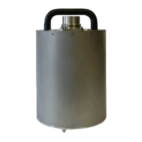
3T Emergency Mass-Locking Introduction 2 Introduction Güralp Systems’ 3-series instruments employ delicate pivots to suspend the masses so, because of the risk of damage while the instrument is being moved, mass-locks are provided to clamp the masses rigidly against the frame. The pivots will almost certainly be damaged if the instrument experiences any significant force while the masses are unlocked. -
Page 6: Emergency Locking
3T Emergency Mass-Locking Emergency Locking 3 Emergency Locking 3.1 Equipment Required You will require the following: A clean environment in which to work, including suitable ESD equipment (dissipative surface, wristband, etc.); 2. A 2mm hexagonal driver; 3. A medium-sized, flat-bladed screw-driver;... - Page 7 3T Emergency Mass-Locking Emergency Locking Warning: For your own safety and that of the instrument, please read and understand all of the following procedure before commencing disassembly. If in any doubt, please contact Güralp technical support for advice. Locate the North indicator on the base of the instrument. This may be a stamped 'N' or a gold-coloured stud.
- Page 8 3T Emergency Mass-Locking Emergency Locking 3. Using the flat-bladed screwdriver, remove the pressure relief screw from the top of the lid: Warning: Instruments are assembled near sea level. If working at altitude, there may be a considerable pressure difference between the inside of the instrument and local atmospheric pressure.
- Page 9 3T Emergency Mass-Locking Emergency Locking The electrical connections between the lid electronics and the rest of the instrument are via a 150mm ribbon cable so it is acceptable to rotate the lid slightly to ease it from its seal. Be careful not to rotate it too far - 10° or so in either direction is a safe limit.
- Page 10 3T Emergency Mass-Locking Emergency Locking 7. Carefully lift the cylinder up and over the sensor, taking care not to catch any of the fine wires. Different models from the 3-series instrument range have different sets of electronics fitted and different revisions have used slightly different mechanical arrangements so what you see at this stage may differ from the illustrations.
- Page 11 3T Emergency Mass-Locking Emergency Locking Identify the three component sensors: the vertical sensor is immediately obvious as its design differs significantly from the horizontals. The two horizontal sensors are usually hand-marked during assembly, as in the photo below: if not, the fine wires from the tops of the sensors can be traced to the feedback board, where the PCB's silk-screening will identify which is which.
-
Page 12: Electrically Driving The Mass-Lock Motors
3T Emergency Mass-Locking Emergency Locking 3.3 Electrically driving the mass-lock motors If it is impossible to lock the masses because of failure of the associated electronics, the mass lock motors can be driven directly in order to lock the masses. In normal... -
Page 13: Manually Driving The Mass-Locks
3T Emergency Mass-Locking Emergency Locking The key parts for the vertical sensor are identified in the picture below: The motor is at 'A' in the left-hand picture. In the right-hand picture, B is the locking pin and C is the supplementary gear-train. - Page 14 3T Emergency Mass-Locking Emergency Locking To lock the East/West sensor component, physically remove the whole locking assembly from the frame by by removing the three screws arrowed in the photo below: It should be possible to turn the cam with a small pair of pliers applied to the coupling sleeve on the gearbox output shaft.
- Page 15 3T Emergency Mass-Locking Emergency Locking Locate the fine wires near the tilt base (marked by arrows in the photo below). Mark one or both wires so as to ensure correct reconnection, then de-solder them from the terminal posts. 2. Similarly, locate, mark and de-solder the four upper fine wires:...
- Page 16 3T Emergency Mass-Locking Emergency Locking 3. Disconnect the cables to the locking motor at the connector shown: PRC-030-0002 Issue B - January, 2017...
- Page 17 3T Emergency Mass-Locking Emergency Locking 4. Undo the three screws (arrowed in the following photographs) holding the component sensor to the instrument base: PRC-030-0002 Issue B - January, 2017...
-
Page 18: Reassembly
3T Emergency Mass-Locking Emergency Locking You should now have easy, unencumbered access to the North/South sensor component. Repeat the locking procedure as for the East/West component. For the vertical component sensor, the procedure is different. First try inserting a flat-headed screwdriver into the teeth of one of the driving gears - it is often possible to rotate the cam in this way. -
Page 19: Revision History
3T Emergency Mass-Locking Revision history 4 Revision history 2010-04-28 New document 2017-01-09 Rebranded. Added “Preliminary Notes” along with additional warnings and cautions. PRC-030-0002 Issue B - January, 2017...
Need help?
Do you have a question about the 3T Emergency Mass-Locking and is the answer not in the manual?
Questions and answers