
Related Manuals for aquilar AquiTron AT-MGS-402

Summary of Contents for aquilar AquiTron AT-MGS-402
- Page 1 AT-MGS-402 AquiTron Gas Detection Controller I N S TA L L AT I O N & O PE RAT I O N I N ST R U CT I O N S...
-
Page 2: Table Of Contents
AT-MGS-402 User Manual Contents Introduction ............. 1 About this Manual ......................1 Conventions ........................1 1.2.1 Iconography ..............................1 General Safety Statements ..................... 2 Product Description ......... 3 Product Overview ......................3 Intended Use ........................4 Design Features ....................... 4 Front Panel ........................5 Components ........................ - Page 3 AT-MGS-402 User Manual Operation ............14 Overview ......................... 14 4.1.1 Main Function .............................14 4.1.2 Power Up ..............................14 4.1.3 Channel number keys ..........................14 Controller Setup ......................14 4.2.1 Modbus Setup .............................14 4.2.2 Relay Setup ..............................16 Gas Detection System Test ................... 17 Modbus ............
-
Page 4: Introduction
1. Introduction 1.1 About this Manual Thank you for investing in an AquiTron AT-MGS-402 Gas Detector Controller. To ensure operator safety and the proper use of the controller, please read the contents of this manual for important information on the operation and maintenance of the instrument. -
Page 5: General Safety Statements
In the case of such occurrence, de-energize the power supply and contact a qualified repair technician or contact Aquilar on 01403 216100. CAUTION: Use ONLY the provided cable glands for electrical and communication wiring. Drilling into the... -
Page 6: Product Description
AT-MGS-402 User Manual 2. Product Description 2.1 Product Overview The AT-MGS-402 Gas Detection Controller displays centralized information about the status of connected AT-MGS-410 gas detectors. The AT-MGS-402 is connected to the AT-MGS-410s via Modbus RTU. The AT-MGS-402 can be used to provide power to each connected AT-MGS-410 gas detector, negating the need for separate power supply at the location of the gas detector. -
Page 7: Intended Use
AT-MGS-402 User Manual WARNING: This instrument is neither certified nor approved for operation in oxygen-enriched atmospheres. Failure to comply may result in EXPLOSION. WARNING: For your safety, DO NOT use this instrument in locations classified as hazardous because it has not been designed for such areas. 2.2 Intended Use The AT-MGS-402 provides audio-visual alerts and information pertaining to the status of a centralized gas detector network. -
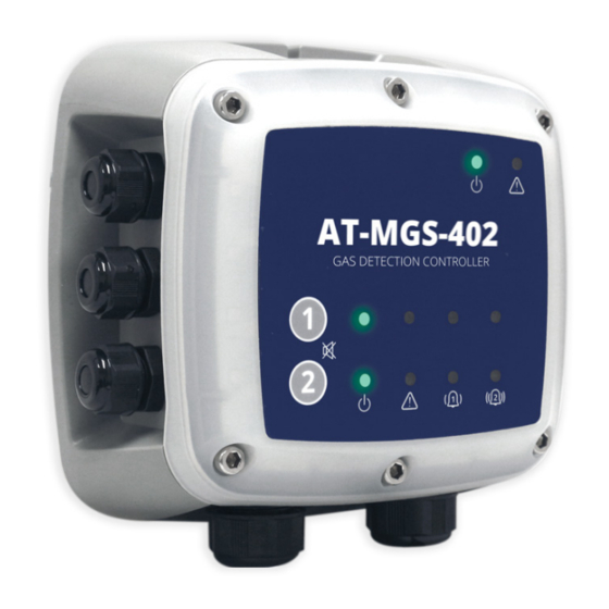
Page 8: Front Panel
AT-MGS-402 User Manual 2.4 Front Panel Figure 2-2 - Front Panel Layout Front Panel Description Integrated visual alarm in bezel Controller Power & Fault LEDS Channel 1 and 2 mute alarm buttons Power, Fault, Low Alarm, High Alarm LEDs; each channel M16 Cable Glands (×6) M20 Cable Glands (×2) -
Page 9: Components
AT-MGS-402 User Manual 2.5 Components Figure 2-3 - AT-MGS-402 Layout Component Description Component Description Analog Outputs (×2) Low Alarm Relay Modbus to Gas Detectors AC Power Line Input Modbus to BMS Power Supply Remote Silence Sensor Power Connections (×2) Audible Alarm M20 Cable Glands (×2) Fault Relay M16 Cable Glands (×6) -
Page 10: Installation
Visually inspect the interior of the enclosure for loose wires or components that may have become dislodged during shipment. If damage is discovered, please contact a qualified repair technician or contact Aquilar for assistance. 3.3 Suitable / Appropriate Locations... -
Page 11: Mounting The Gas Detection Controller
AT-MGS-402 User Manual 3.4 Mounting the Gas Detection Controller NOTE: A certified AC power disconnect or circuit breaker should be mounted near the controller and installed following applicable local and national codes. If a switch is used instead of a circuit breaker, a properly rated CERTIFIED fuse or current limiter is required to be installed as per local or national codes. -
Page 12: Sensor Output & Modbus Connections
AT-MGS-402 User Manual 5. Plug the power terminal block back into the printed circuit board (PCB). Figure 3-1 - Power Terminal Block 3.6 Sensor Output & Modbus Connections 3.6.1 AT-MGS-402 Gas Detection Controller Network The AT-MGS-402 Modbus communications network is connected to the AT-MGS-410 gas detectors using a shielded twisted pair instrument cable (Belden 3106A or equivalent). - Page 13 AT-MGS-402 User Manual 3. Reconnect +24VDC terminal to the PCB and repeat for a second AT-MGS-410 gas sensor if needed. Figure 3-2 - +24 VDC Terminal Block 3.6.1.2 Connecting the Modbus network from the AT-MGS-402 to the AT- MGS-410 1. Locate the Modbus/Sensor terminal block in the AT-MGS-402 controller (item 2 in “Figure 2-3 - AT-MGS-402 Layout”...
-
Page 14: Integration With Building Management System
AT-MGS-402 User Manual GND SH Refer to the AT-MGS-410 User Manual or Quick Start Guide for location and connection of the corresponding Modbus terminal block in the AT-MGS-410 gas sensor. NOTE: Ensure that the corresponding wire colors noted above are connected to the correct ‘B’ and ‘A’... -
Page 15: Reinstalling At-Mgs-402 Lid
AT-MGS-402 User Manual There are (3) form C relay contacts rated 10A at 240VAC and (2) Analog Outputs (4-20ma, 1-5V, 2-10V). In addition there is (1) Remote Silence input to interface with a momentary push button that may be in a different location than the AT-MGS-402. - Page 16 AT-MGS-402 User Manual 5. Reconnect the ribbon cable from the sensor to the PCBA as shown. Figure 3-5 - Ribbon Cable Orientation WARNING: DO NOT allow the lid / sensor to hang from the ribbon cable. Failure to comply may result in damage to the product. 6.
-
Page 17: Operation
AT-MGS-402 User Manual 4. Operation 4.1 Overview 4.1.1 Main Function Every second the AT-MGS-402 Gas Detection Controller collects gas concentration and status information from each connected gas detector. Connection status, fault and alarm conditions are indicated by the LED matrix for each channel. Detector data and controller status information can also be communicated via Modbus, to a master or BMS device. - Page 18 AT-MGS-402 User Manual Figure 4-1 - AT-MGS-402 Back of Lid Label Using switch 1 (SW1) on the underside of the lid of the controller use setting 4 to acknowledge whether the AT-MGS-402 will need to have the terminating resistor engaged. Please see Modbus protocol for best practice.
-
Page 19: Relay Setup
AT-MGS-402 User Manual 2 Stop Bits 9600 Bits Per Second 19200 Bits Per Second NOTE: All of the above settings must match the BMS system to work correctly. 4.2.2 Relay Setup Additional hardware configuration. 4.2.2.1 Form C Relays The (3) form C relays that are included in the AT-MGS-402 (fault, low alarm, high alarm) can be configured to be fail safe (if power is lost on the relay it will be set to its fault or alarm state until power is restored). -
Page 20: Gas Detection System Test
AT-MGS-402 User Manual Over-range 20.5 mA Normal 4-20 mA 1-5V 2-10V IMPORTANT: The Analog outputs come with a jumper installed from the factory. This ensures that the AT-MGS-402 does not go into alarm mode upon power but before connecting the analog outputs –... - Page 21 AT-MGS-402 and AT-MGS-410 audio / visual alarm functions as well as verify the proper function of connected relay peripherals and analog and Modbus monitoring devices. Though Aquilar recommends a full system test with calibration span gas, there may be circumstances where the customer wishes to check the relay peripheral device function without applying span gas.
-
Page 22: Modbus
AT-MGS-402 User Manual 5. Modbus 5.1 Modbus Overview Modbus RTU protocol is utilized both for down line detector communication and up line BMS communication. Communication parameters may be set via the configuration switches. The AT-MGS-402 controller acts as a Modbus master device on the detector side, and as a Modbus slave device on the BMS side. - Page 23 AT-MGS-402 User Manual Register Func Code 04 Item Group Notes Address (read input registers) 30003 Sensor 1 Modbus error code Sensor 1 Exception code from Modbus standard 30004 Sensor 1 concentration Sensor 1 0-65535 30005 Sensor 1 status code Sensor 1 0 = Offline 1 = Warm-up 2 = Online...
- Page 24 AT-MGS-402 User Manual Register Func Code 04 Item Group Notes Address (read input registers) 30027 Sensor 1 SID Text Char 7,8 Sensor 1 ASCII characters 30028 Sensor 1 UID Text Char 1,2 Sensor 1 ASCII characters 30029 Sensor 1 UID Text Char 3,4 Sensor 1 ASCII characters 30030...
- Page 25 AT-MGS-402 User Manual Register Func Code 03/06 Item Group Notes Address (Read/preset) 40005 Parity Controller- 0 = None related 1 = Odd 2 = Even 40006 Controller UID Char 1,2 Controller- ASCII characters related 40007 Controller UID Char 3,4 Controller- ASCII characters related 40008...
- Page 26 AT-MGS-402 User Manual Register Func Code 02 Item Group Address (read input status) 10001 Sensor 1 Low Alarm Flag (0 or 1 = alarm) Sensor 1 10002 Sensor 2 Low Alarm Flag (0 or 1 = alarm) Sensor 2 10003 Sensor 1 High Alarm Flag (0 or 1 = alarm) Sensor 1 10004...
-
Page 27: Diagnostics & Troubleshooting
AT-MGS-402 User Manual 6. Diagnostics & Troubleshooting 6.1 FAULT CODES Code Critical Fault Possible Causes Remedy 0001 CHASSIS TEMP Chassis temperature outside the range Reduce ambient temperature or check for of -40 to +50C power supply malfunction. 0002 RS485 MSTR BUFR Buffer overflow communicating with Disable all but one channel, use Modbus detectors... -
Page 28: Additional Information
AT-MGS-402 User Manual 7. Additional Information 7.1 Disposing of Instrument EU-wide regulations governing the disposal of electrical and electronic appliances which have been defined in the EU Directive 2012/19/EU and in national laws have been effective since August 2012 and apply to this device. -
Page 29: Parts And Accessories
AT-MGS-402 User Manual 8. Parts and Accessories 8.1 Part Numbers Part # Description 40801 AT-MGS-402 Controller... - Page 30 AT-MGS-402 User Manual Unit 30, Lawson Hunt Industrial Park, Broadbridge Heath, Horsham, West Sussex, RH12 3JR +44 (0) 1403 216100 info@aquilar.co.uk www.aquilar.co.uk...
Need help?
Do you have a question about the AquiTron AT-MGS-402 and is the answer not in the manual?
Questions and answers