Advertisement
Quick Links
1. Overview
SK202 is a pair of RF module
1Gbps data rate Ethernet to 60GH
of SK202 is an RJ45 Gigabit E
SK202 modules are based on lea
output consist in an RF transm
centimeter.
2. Features
Ÿ 60GHz V-Band tran
Ÿ Gigabit Ethernet sho
Ÿ Full duplex, horizont
Ÿ RJ45 MDI interface
Ÿ Used in pairs
3. Application
Ÿ LED panels for modul
Ÿ Video surveillance c
Ÿ Contactless Etherne
4. Block diagram
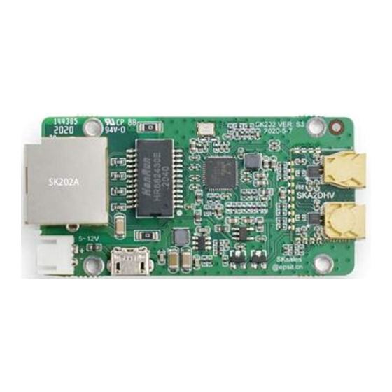
Board outlook:
SK202 Specification
SK202
GigE
contactless connectivity
ules with H&V horn antenna and G-PHY to ac
GHz millimeter Wave RF signal conversion.
Ethernet Connector supporting 10/100/1000Ba
eading edge ST60A2 mmW RF transceiver an
mission of the corresponding SGMII signal ove
nsceiver with ST60A2
ort range contactless connectivity, preferred 3
ntal transmission, Controlled Auto negotiation
ace Ethernet input
dular display walls
ce camera and robotics
et applications
achieve
The input
ase-T.
nd the
er several
3cm
tion
1 of
f 3
Advertisement

Related Manuals for EPS SK202 Series


Summary of Contents for EPS SK202 Series
- Page 1 SK202 GigE contactless connectivity 1. Overview SK202 is a pair of RF module ules with H&V horn antenna and G-PHY to ac achieve 1Gbps data rate Ethernet to 60GH GHz millimeter Wave RF signal conversion. The input of SK202 is an RJ45 Gigabit E Ethernet Connector supporting 10/100/1000Ba ase-T.
- Page 2 5. Assembly PCB installation: Unit: mm Note: (1) If a metal cover is used, a w window should be added for microwave signa al. Plastic or other microwave insensitiv itive materials can be used to fill the window. (2) The DC socket and the USB B MICRO-B socket are connected together.
-
Page 3: Auto-Negotiation
Fosc Carrier Frequency 60.3 60.4 60.5 * when power supply is 12V and Ethernet is active. 7. Auto-negotiation The Ethernet PHY supports 1Gbps, 100Mbps and 10Mbps speeds. In order for two Ethernet modules to communicate correctly, care must be taken that the PHY on both modules negotiate the same speed. - Page 4 This document guides use ers how to use the SK202A/B modules. T The pair of modules transmits Gigabit Eth thernet signals at a distance of several centim meters in a contactless way. SK202 opens a new scene for network connection applica cations.
- Page 5 Figure 2. Physical picture of SK202 non-contact connector The Network PHY chip embed dded in the SK202 is set in Auto-negotiation m mode and is able to support 10/100/1000M Mbps. In order for the SK202A and SK202B communicate they must operat te at the same speed.
- Page 6 Thanks to the controlled a auto-negotiation on the laptop, one can ensu ure the link with the SK202 will be set up p at the same speed than the one between th the second SK202 and the camera. Figure 4. Controlled auto-ne egotiation is required when the 2 devices do not adverti tise the same...
- Page 7 PCs to complete the test. You c can download from the address as below: https://iperf.fr/iperf-downlo wnload.php Iperf3 test method: Figure 6. Iperf3 test Schematic diagram with SK202 Refer to the figure 6 to con onnect to the network. The network adapters of f two PCs need the same speed, such as G Gigabit Ethernet controller.
- Page 8 Figure 7. Iperf3 test Schematic diagram with RJ45 cable For the RF waves to propa agate correctly from one module to the other, , care must be taken not to introduce any metallic obstacle in a Keep Out Area (KOA OA), in green on the figures below.
- Page 9 with ABS or other microwave insensitive materials to maintain water tightness. This opening should follow these guidelines: · The casing must be placed at around 2.7mm from the PCB to ensure a free space of 0.8mm between the Horn antennae body and the ABS housing. ·...
Need help?
Do you have a question about the SK202 Series and is the answer not in the manual?
Questions and answers