Advertisement
Quick Links
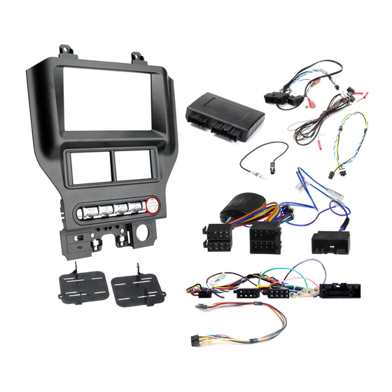
1. Fascia Panel
2. Right Bracket
3. Left Bracket
4. Four Switch Trim
5. Back Cover
6. PCB Spacer
7. Pocket
APPLICATION
Ford Mustang
For vehicles with Concert,Chorusor Symphony factory stereo and Mini ISO connector
RECOMMENDED TOOLS
•Panel Removal Tool
FEATURES
•Allows for the installation of a double DIN aftermarket stereo
•Replaces HVAC control unit
•Retains climate controls, steering wheel controls, heated seats, vehicle OE
personalisation menus and settings
•Accomodates OEM toggle or OEM push button switches
•Includes mountingbrackets and fitting accessories
•Finished in gun metal to match vehicle dashboard
The information provided in this document is subject to change without notice due to manufacturer changes and/or improvements to the product/s. This
instruction manual is based on documented data and research. The manufacturer of this product cannot be held responsible for any changes made to the
vehicle by the manufacturer or damages that may occur through the installation of this product in accordance with the steps outlined herein.
Integrated Touch Screen Control Kit
2015>
(Right Hand Drive Models Only)
•Screwdriver
DISCLAIMER
for Ford Vehicles
Note: Application data is subject to change at any time
•Cutting Tool
FP8419K
FP8419K_IG_en-GB_v1
Advertisement

Summary of Contents for Aerpro FP8419K
- Page 1 FP8419K Integrated Touch Screen Control Kit for Ford Vehicles 1. Fascia Panel 2. Right Bracket 3. Left Bracket 4. Four Switch Trim 5. Back Cover 6. PCB Spacer 7. Pocket APPLICATION Note: Application data is subject to change at any time Ford Mustang 2015>...
-
Page 2: Prior To Installation
PRIOR TO INSTALLATION Read the manualpriorto installation. Technical knowledgeis necessary for installation. The place of installation must be free of moisture and away from heat sources. Please ensure that the correct tools are using duringthe installation to avoid damage to the vehicle or product.Connects2 can not be held responsible for the installation of this product. *WARNING* **DASH MODIFICATIONIS REQUIRED FOR FULL INSTALLATION OF A DOUBLE DIN STEREO WHEN USING THIS PRODUCT** See Step 7 for Details... - Page 3 INSTALLATION GUIDE 4. Unclip and remove the plastic plate located inbetween the USB plug-inand the cigarette lighter 5. Remove the four screws securing the OEM panel to the dash (circled), then unplugand remove the panel 6. Remove the OEM display and the CD receiver by unscrewing the four screws for each component, then unplug all wiring and remove.
- Page 4 INSTALLATION GUIDE 8. Remove the ten screws and the 12V socket locat- ed behind the OEM climate control panel and retain for installation. Then remove the PCB board back cover. NB: The amountof screws may vary between vehicle models. Retain the 12Vsocket from the OEM panel and place it on the aftermarket panel once removedfrom the OEM panel 9.
- Page 5 INSTALLATION GUIDE 11. Lift and remove the drive train/ignition controls and rubberpad from the OEM panel and retain for later install NB: Remove rubberand plastics blocking pieces needed in order to remove the ignition controls 12. Place the drive train/ignition control trim into the fascia panel 13.
- Page 6 INSTALLATION GUIDE 14. Place the rubberpad from the OEM drive train controls onto the back of the buttons, being careful not to knock over the spacers placed in the previous step. 15. Carefully align the circuit board over the rubber 16.
- Page 7 INSTALLATION GUIDE 17. For Single DIN Installation: Attach the brackets provided to the pocket (A), then secure the stereo to the brackets (B). Lastly, secure stereo assembly into dash cavity (C). For DoubleDIN Installation: Attach the brackets provided to the aftermarket stereo (D), then secure stereo assembly into dash cavity (E).
- Page 8 CONNECTING THE PATCH LEAD Here are some example of how to make various patch leads: Example 1: Alpine -Cut Link J2, then use the Jack Connector to connect the patch lead to the head unit Example 2: Kenwood -Cut Link J1 and J2, then use the wire connector to connect the patch lead to the head unit STEERING WHEEL CONTROL CONFIGURATION Track -...
-
Page 9: Wiring Diagram
WIRING DIAGRAM FP8419K_IG_en-GB_v1... - Page 10 CLIMATE/CONVENIENCE CONTROLS The touchscreen interface replaces the factory climate, convenience and personalisation controls built into the factory Ford stereo/dash panel. This solution provides improvedergonomics whilst addingtouchscreen capabilities uniqueto this sys- tem. Read the followingsections to familiarise yourself with the operatingcontrols and settings. LEFT TOUCHSCREEN BUTTONLAYOUT MENU HH:MM...
- Page 11 CLIMATE/CONVENIENCE CONTROLS RIGHT TOUCHSCREEN BUTTON LAYOUT 23.0 22.0 AUTO AUTO DUAL 11. Touch the vent control mode icons to select 16. Decrease the fan speed using the Fan -button desired vent mode. Graphics are displayed according to the selected vent and airflow pattern. Air can be 17.
-
Page 12: Menu Navigation
MENU NAVIGATION Press the MENU button to access the Configurationmenuand adjust Vehicle, ITC Interface, Language and Version settings. The following screenshots are sample menu displays to assist in the navigation of the user interface. Use the Return Arrow to go back to the previous menu. Press the X to close the menu window and return to the TFT colour touch screen home screen. - Page 13 VEHICLE CONFIGURATION SETTINGS CHART Use the charts on the following pages of this instruction manual to navigate throughthe various menus and settings offered by the kit. VEHICLE SETTINGS (INSTALLER MENU) Toaccess the Installer Menu,quick press the Menu icon on the touch screen display four times. A popup will appear with the notification: "Installer Menu Enabled".
- Page 14 ITC SETTINGS CHART LANGUAGE & SOFTWARE SETTINGS CHART FP8419K_IG_en-GB_v1...
- Page 15 NOTES FP8419K_IG_en-GB_v1...
- Page 16 NOTES FP8419K_IG_en-GB_v1...
Need help?
Do you have a question about the FP8419K and is the answer not in the manual?
Questions and answers