Table of Contents
Advertisement
Advertisement
Table of Contents

Related Manuals for Strand C21


Summary of Contents for Strand C21
- Page 1 C21 / EC21 ADVANCED TECHNOLOGY DIMMER RACK OPERATION GUIDE...
-
Page 2: Technical Assistance
Strand can assure you that every eff ort has been made to ensure that the equipment has been designed to meet the high- est professional standards and that dimmer racks and their components have been assembled, inspected, and tested in accordance with our strict quality assurance program. - Page 3 A power control device used in Strand dimmers that contains two silicon con- trol rectifiers (SCRs), control circuitry, and optical isolation circuitry. A digital architectural control system for use with C21/EC21 dimmer racks.
-
Page 4: Specifications
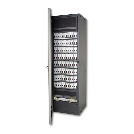
Strand website at www.strandlighting.com. RACK COMPONENTS Th e C21 / EC21dimmer rack is a listed, free standing, factory assembly of steel and aluminum construction fi nished in a fi ne textured, scratch resistant coating. Each C21 / EC21dimmer rack consists of a rack processor housing (RPH) with one or two rack processor modules (RPM), a fan module, and up to 24 or 48 dimmer modules. -
Page 5: Dimmer Modules
DIMMER MODULES Th e power modules are the high power switching section of the C21 / EC21 dimming system. Th e power block in this module is the interface between the high power AC and low power control. It is driven by low level signals (5mA, 3-24V) and switches high level signals (up to 100A, 120/240VAC). -
Page 6: Fan Module
FAN MODULE C21 / EC21 dimmer racks are cooled by one or two low-noise variable speed fans in a fan module inside the rack. Th e cooling system is designed to let the rack continue functioning if any one of the fans fail. Cooling air is pulled up through the dimmer stack and exhausted through venting at the top of the rack. - Page 7 RACK PROCESSOR HOUSING Each C21 / EC21 dimmer rack contains a rack processor housing (RPH) with all of the control electronics for the rack. Th is RPH contains the processor module(s) (RPM), control station power supplies, and control interconnection card (CIC) for the rack, and is shipped separately from the rack to minimize the possibility of damage.
-
Page 8: Power Supplies
FIGURE 6. RACK PROCESSOR MODULE POWER SUPPLIES Each C21 / EC21dimmer rack can have up to three power supplies, depending on the accessories provided. Th ese power supplies are mounted on the rack processor housing. CONTROL INTERCONNECTION CARD (CIC) Th e electronics chassis also contains the control interconnection card (CIC). Th is is where the contractor terminates all control wiring for the rack. - Page 9 If any other LED does not illuminate correctly, switch OFF the power immediately and check the installa- tion again. If the fault persists and all wiring seems correct, call Strand Lighting or your local Authorized Service Center (www.strandlighting.com).
-
Page 10: Safety Features
• 96 Panic Select switches SAFETY FEATURES In order to minimize the impact of failures to any part of C21/EC21 dimmer racks, a number of security features, some of which are optional, are provided. Standard safety features for C21/EC21 dimmer racks include: •... -
Page 11: Operational Features
It is located on the top of the Rack Processor Housing (RPH) and contains: • An Ethernet switch which connects to a Strand ShowNet system. Th is switch allows for easy connections between dimmer racks. It also connects to the network receptacle located in the upper left rear of the dimmer rack. - Page 12 • 96 Panic Select switches SAFETY FEATURES In order to minimize the impact of failures to any part of C21/EC21 dimmer racks, a number of security features, some of which are optional, are provided. Standard safety features for C21/EC21 dimmer racks include: VISION.NET...
-
Page 13: Controls And Displays
C21 / EC21 ADVANCED TECHNOLOGY DIMMER RACK OPERATION GUIDE PROGRAMMING CONTROLS AND DISPLAYS You can access the range of C21 / EC21dimmer rack programmable features using the Jog Wheel and LCD display. Menus are shown in English. FIGURE 8. RACK PROCESSOR MODULE FRONT PANEL LOCK MENU To avoid accidental or unauthorized use, you can lock the menu. - Page 14 C21 / EC21 ADVANCED TECHNOLOGY DIMMER RACK OPERATION GUIDE MAIN MENU RACK IDENTITY DIMMER CONFIG LOCAL CONTROL VIEW RACK NAME SET DIMMER PATCH SET DIMMER LEVEL VIEW RACK LOCATION VIEW FULL OUTPUT V SET DIMMER LEVEL RANGE VIEW MAIN BREAKER ID...
-
Page 15: Network Config Menu
NOTE: Th e default Gateway IP address should not be changed unless instructed to do so by Strand Lighting. VIEW MAC ADDRESS. View the MAC Address assigned to the C21 and EC21 processor. Th e MAC address is set at the factory is not accessible. - Page 16 C21 / EC21 ADVANCED TECHNOLOGY DIMMER RACK OPERATION GUIDE dimmer rack slots. SET FAN CONTROL. Adjust the minimum fan speed. SET LCD BACKLIGHT. View or edit the LCD backlight. LOCK MENU. Enable or disable the keypad lockout. SET PREFERRED PROCESSOR. Allows you to select which processor, main or backup, will be active.
- Page 17 VIEW RESPONSE TIMES. View the response times for the dimmers, six dimmers at a time. SET RESPONSE TIMES. Th e response time of a dimmer is the rate at which it responds to increases or decreases in the control level. C21 / EC21dimmer racks provide fi ve response times: Fast = 30ms...
-
Page 18: Input Config Menu
C21 / EC21 ADVANCED TECHNOLOGY DIMMER RACK OPERATION GUIDE User5 = User Defined Dimming Curve #5 VIEW CUT LEVELS. View the Cut Levels for the output dimmers, up to 6 at a time. SET CUT LEVELS. Set the Cut Levels for the output dimmers. Note that the cut level is the percentage at which, below this number, the output will automatically be set to ‘0’... -
Page 19: Factory Menu
C21 / EC21 ADVANCED TECHNOLOGY DIMMER RACK OPERATION GUIDE conventional lighting control system. SET DIMMER LEVEL RANGE. Set a range of dimmers to INPUT or to a local level between 0% and FULL. NOTE: Setting dimmer levels to something other than INPUT overrides the control inputs, including presets, you can easily lose control of dimmers by forgetting to set them back to INPUT. -
Page 20: Main Screen
C21 / EC21 ADVANCED TECHNOLOGY DIMMER RACK OPERATION GUIDE CONFIGURATION WEB PAGES Th is section provides basic information on the C21/EC21 Web Pages. MAIN SCREEN STATUS Select [STATUS] to gain access to the following options: STATUS > DIMMER W W W. S T R A N D L I G H T I N G .C O M... - Page 21 C21 / EC21 ADVANCED TECHNOLOGY DIMMER RACK OPERATION GUIDE STATUS > SYSTEM STATUS > VERSIONS STATUS > SYS EVENTS STATUS > DIM EVENTS W W W. S T R A N D L I G H T I N G .C O M...
- Page 22 C21 / EC21 ADVANCED TECHNOLOGY DIMMER RACK OPERATION GUIDE STATUS > EVENT LOG SYSTEM Select [SYSTEM] to gain access to the following options: SYSTEM > PARAMETERS SYSTEM > MODULES W W W. S T R A N D L I G H T I N G .C O M...
- Page 23 C21 / EC21 ADVANCED TECHNOLOGY DIMMER RACK OPERATION GUIDE SYSTEM > DATE/TIME SYSTEM > CONSTRUCTION SYSTEM > BACKUP LOOKS W W W. S T R A N D L I G H T I N G .C O M...
- Page 24 C21 / EC21 ADVANCED TECHNOLOGY DIMMER RACK OPERATION GUIDE SYSTEM > FIRMWARE CONTROL Select [CONTROL] to gain access to the following options: CONTROL > LOCAL SAVE/RESTORE Select [SAVE/RESTORE] to gain access to the following options: W W W. S T R A N D L I G H T I N G .C O M...
- Page 25 C21 / EC21 ADVANCED TECHNOLOGY DIMMER RACK OPERATION GUIDE SAVE/RESTORE > SAVE BACKUP CFG Note that this will save the current operating parameters to a backup area on the rack processor, overwriting any previ- ously saved parameters. SAVE/RESTORE > RESTORE BACKUP CFG Note that you will lose all changes made since the last confi guration save.
- Page 26 C21 / EC21 ADVANCED TECHNOLOGY DIMMER RACK OPERATION GUIDE DIMMER Select [DIMMER] to gain access to the following options: DIMMER > CIRCUITS DIMMER > MODES DIMMER > DYNAMICS W W W. S T R A N D L I G H T I N G .C O M...
- Page 27 C21 / EC21 ADVANCED TECHNOLOGY DIMMER RACK OPERATION GUIDE DIMMER > USER PROFILES DIMMER > TOLERANCE DIMMER > REPORTING PATCH Select [PATCH] to gain access to the following options: PATCH > DIMMER Place holder text. W W W. S T R A N D L I G H T I N G .C O M...
- Page 28 C21 / EC21 ADVANCED TECHNOLOGY DIMMER RACK OPERATION GUIDE VISION.NET Select [ VISION.NET] to gain access to the following options: VISION.NET > CONFIGURE VISION.NET > PATCH W W W. S T R A N D L I G H T I N G .C O M...
- Page 29 Th e information presented in this document is not intended as any commercial off er and does not form part of any quotation or contract, unless otherwise agreed by Signify. Data subject to change. C21 / EC21 ADVANCED TECHNOLOGY DIMMER RACK OPERATION GUIDE DOCUMENT NUMBER: 91200545005...
Need help?
Do you have a question about the C21 and is the answer not in the manual?
Questions and answers
How to go about a to turn the lights back on from the c21 processor?