Table of Contents
Advertisement
Ecro RV
Technical manual
Digital device for the control and monitoring of fume
hoods in laboratories.
• Air control compliant with the EN14175 standard.
• Compact and low cost device.
• High-speed hot wire probe.
• Closed loop control.
• Air speed digital display in m/s.
• Sash window automation available.
• Suitable for every laboratory applications.
CD 908 13720 BELCODENE
.: 04 42 70 63 90
: 04 42 70 63 95
contact@comelec.fr www.ecro.fr
Tél
Fax
Advertisement
Table of Contents

Subscribe to Our Youtube Channel
Summary of Contents for Comelec ECRO RV
- Page 1 Ecro RV Technical manual Digital device for the control and monitoring of fume hoods in laboratories. • Air control compliant with the EN14175 standard. • Compact and low cost device. • High-speed hot wire probe. • Closed loop control. • Air speed digital display in m/s.
-
Page 2: Table Of Contents
SUMMARY 2 ..General technical information ..........page 4 3 ..Characteristics ................page 4 3.1 .. Electrical characteristics ............page 4 3.2 .. Nominal features ..............page 4 3.3 .. Velocity operating mode ............page 5 3.4 .. Electrical wiring ................page 8 3.5 .. Dimensions ................page 9 4 .. - Page 3 Gamme ECRO ECRO RS ECRO RV ECRO RD CHARACTERISTICS Supply 230 V Display DELs DELs DELs 2 lines 2 lines 2 lines 2 lines 2 lines 2 lines Double run command relay Light relay Alarm relay Permanent 0-10V PID 0-10V signal...
-
Page 4: General Technical Information
2. GENERAL TECHNICAL INFORMATION sERVOMOTEUR • Supply 230 VAC- 50Hz included Operating time ................ 8s. • Data backup in EEPROM in case of power outage Shaft size ........Ø10 à 20mm / □10 à 16mm. • Visual and audible alarm for a functioning > 40 cm Noise level during operation..........45dB. -
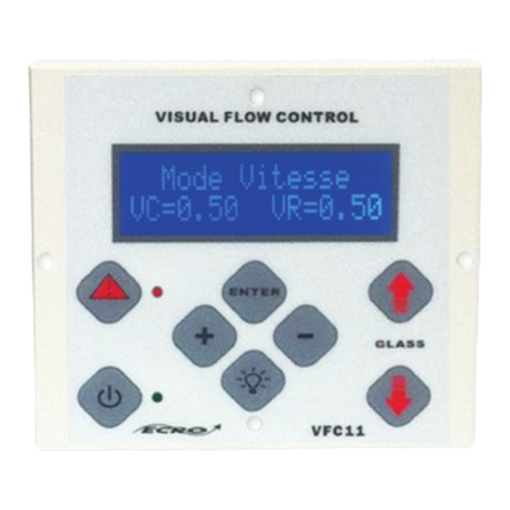
Page 5: Velocity Operating Mode
- The systems with propellers are used to measure velocities above 1 m/s. Control unit ECRO-RV With the velocity probe developed by Comelec, the least Display panel VFC11 change in the sash position begets a fluctuation of air which Low sash contact is translated by the probe into an electrical signal 0.5Vdc. - Page 6 The motor part. Motorized damper : The servomotor has been chosen from the proportional range of the brand Joventa, its reference is SM1.2. Applications: this range of elec- trical servomotors has been designed for air dampers in HVAC applications (Heating, Ventilation and Air-Conditioning). Joventa’s universal adapter is particularly convenient.
-
Page 8: Electrical Wiring
3.4. Electrical wiring sash opening sash Light Alarm Inverter run contact lowering contact contact Constant source of command contacts supply (10v-500mA) DOWN LIGHT ALARM FAN1 FAN2 0V I ECRO - RV L N G SENSOR DISPLAY 0V Vs HIGH LOW PIR_IN TOR4 FUSE 0-10V... -
Page 9: Dimensions
3.5. Dimensions Supply enclosure front view Side view HMI enclosure front and side view... -
Page 10: User Instructions And Setup
4. UsER INsTRUCTIONs AND sETUP CThis leaflet is dedicated to the installer in charge of the setup of the Ecro-RV, a product for laboratories, developed by the Company COMELEC. These few pages explain the different steps for an optimal set- OUTSIDE ting of this control device. - Page 11 Electrical wiring Ecro-RV. RJ12/ 6-point DIN cable To hot-wire probe 8-point RJ45 cable to display device...
- Page 12 RJ12/ 6-point DIN cable To hot-wire probe 8-point RJ45 cable to display device...
-
Page 13: Controller Setup
CAUTION : the electrical wiring must be done in accordance to the installation leaflet. When the device is powered, the IMH VFC11 makes a long bip then the LCD display lits. First, the display shows the version of software and the reference of the product. ECRO RV -----COMELEC----- VERSION 2012 V9... -
Page 14: Menu Access
4.4.1 Menu access In order to protect the device against inadvertent disadjustments, the access to the menu IHM VFC11 is protected by a PIN code. NB: The default PIN code is 0000 but it is possible to modify it. To have access to the menu, do as follows: Press button ENTER, the following screen is displayed : ENTER YOUR CODE --CONFIDENTIAL--... -
Page 15: Settings
4.4.2 settings Alarm response time setting. setting the velocity setpoint. The alarm response time is the period you accept to stay in default before informing the user. It can be modified by the installer. The containment change according to the kind of fumehoods used. - Page 16 min : 1ms max : 250ms Reaction time setting. sash closing settings. The reaction time is the period taken by the device to detect a default and apply a correction. It can be modified by the The ECRO-RV device can include a command mechanism to installer.
- Page 17 Setting range for the closing delay: min : 1min max : 250min CAUTION : this value is calibrated by a qualified tech- Hot-wire probe corrective coefficient setting. nician during the factory’s calibration phase. Buzzer activation . The velocity probe consists of a wire heated at a temperature higher than the ambient temperature.
- Page 18 HMI locking. VMin tension setting. To prevent the control device from being put into standby The velocity control device delivers a PID type analog signal mode, le button ON/OFF can be locked. varying between 0 and 10 V. However, for some applications, a minimum tension threshold is necessary to guarantee a To do so, proceed as follows : enter the menu as explained minimum exhaust flow rate.
-
Page 19: Troubleshooting
4.5 Troubleshooting. The table above helps the user to troubleshoot possible connectivity problems linked to the control device when the ECRO-RV is put into service. Problem : The VFC11 HMI does not light up and does not emit any bip. Cause : The device is not powered. - Page 20 The table above helps the user to troubleshoot possible aeraulic problems when the ECRO-RV is put into service. Problem : Low air suction The fan is ill-suited Cause : The fan rotates in the wrong direction There are problems in the aeraulic network. Select a suited fan Solution : Reverse the direction of rotation...
-
Page 21: Additional Information
5. Additional information Maintenance Avoid any aggressive solvent When cleaning with products based on formalin (pieces or ducts) protect the device and the probe. Device range □ ECRO-RV Origin □ ECRO- RV Progressive □ ECRO-RV Exclusive Options □ Fumehood motorization □...
Need help?
Do you have a question about the ECRO RV and is the answer not in the manual?
Questions and answers