Table of Contents
Advertisement
Advertisement
Table of Contents

Summary of Contents for Agromehanika AG-TRONIK S1
- Page 1 Instructions for use Remote electronic regulation AG-TRONIK S1...
- Page 2 AG-TRONIK...
-
Page 3: Table Of Contents
3.2. Speed sensor (additional equipment) ........................11 3.3. GPS (additional equipment) ..........................12 3.4. MOUNTING TO THE VACUUM HOLDER (additional equipment) ............... 13 BUTTONS OF AG-TRONIK S1 ............................14 4.1. Buttons .................................. 14 4.2. Setup fields ................................15 4.3. Information fields ..............................16 PARAMETER SETTINGS - PROGRAMMING ....................... - Page 4 AG-TRONIK 5.10. Flow Analysis ................................ 32 5.11. Daily Counters ............................... 32 DESCRIPTION OF HANDLING WITH AG-TRONIK S1 ....................33 6.1. Manual Regime ..............................33 6.2. Automatic regime ..............................34 6.3. SPRAYING GUIDELINES ............................. 34 6.3.1. Preparation for Spraying..........................34 6.3.2.
-
Page 5: Safety Instructions
AG-TRONIK 1 SAFETY INSTRUCTIONS 1.1. Basic Safety Instructions Before first use read the instruction manual carefully • Don't use AG-TRONIK and drive on the road. If so, stop the tractor safely. • Before maintenance or repair of tractor, disconnect the signal cable between tractor and AG-TRONIK. -
Page 6: Structure And Meaning Of Safety Advices
AG-TRONIK 1.2. Structure and meaning of safety advices All safety advices, which are in this manual, are introduced below. WARNING This signal word identifies medium-risk hazards, which could potentially cause death or serious physical injury, if not avoided. CAUTION This signal word identifies low-risk hazards, which could potentially cause minor or moderate physical injury or damage to property, if not avoided. -
Page 7: User Requirements
AG-TRONIK 1.3. User Requirements • Learn how to operate with terminal correctly. The terminal may not be operated by anyone who has not read the Operating Instructions. • Please read and carefully observe all safety instructions and warning contained in these Operating instructions and the manuals of any connected vehicles and farm equipment. -
Page 8: Predstavitev Ag-Tronik-A S1
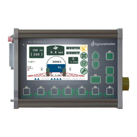
AG-TRONIK 2 PREDSTAVITEV AG-TRONIK-a S1 • AG-TRONIK is processor-controlled device for monitoring and automatic balancing of spray on machines for chemical protection of plants. • It is used on combination with pressure regulator PR10EC. • Take a few moments to familiarize yourself with component parts of AG-TRONIK. •... - Page 9 AG-TRONIK • Connectors and buttons for operating with AG-TRONIK are shown in pictures below (Figure 2 and Figure 3) Figure 2 Figure 3 • Connectors and buttons for operating with AG-TRONIK are introduced in table below (Table 2). CONNECTOR FUNCTION TYPE OF CONNECTOR SPEED SENSOR 4-pin.
-
Page 10: Ag-Tronik-A S1 Connection
3 AG-TRONIK-a S1 CONNECTION If you are not skilled in such work, we recommend that the electronic regulation is installed by an authorized service of Agromehanika. If you have decided to install it yourself, a brief installation description is given further on. -
Page 11: Speed Sensor (Additional Equipment)
AG-TRONIK 3.2. Speed sensor (additional equipment) • Connect power supply in to the corresponding input of the AG-TRONIK (Figure 5). • Connect regulator cable in to the corresponding input of the AG-TRONIK (Figure 5). • Connect speed sensor in to the corresponding input of the AG-TRONIK (Figure 5). Figure 5... -
Page 12: Gps (Additional Equipment)
AG-TRONIK 3.3. GPS (additional equipment) • Connect power supply in to the corresponding input of the AG-TRONIK (Figure 6). • Connect regulator cable in to the corresponding input of the AG-TRONIK (Figure 6). • Connect GPS device (both, power and signal cable) in to the corresponding input of the AG-TRONIK (Figure 6). -
Page 13: Mounting To The Vacuum Holder (Additional Equipment)
AG-TRONIK 3.4. MOUNTING TO THE VACUUM HOLDER (additional equipment) • AG-TRONIC and hydraulic control panel may be mounted on the side window of the tractor by using a vacuum carrier (020.00.123). • Screw the AG-TRONIK with the four screws in the groove on the back side (Figure 7). •... -
Page 14: Buttons Of Ag-Tronik S1
AG-TRONIK 4 BUTTONS OF AG-TRONIK S1 • AG-TRONIK enables a full control of spraying by using buttons and touch screen. • In subchapter 4.1 buttons of AG-TRONIK are introduced, in subchapters 4.2 and 4.3, setup and information fields are introduced. -
Page 15: Setup Fields
AG-TRONIK 4.2. Setup fields • The setup fields are used to enter the spray parameters (Figure 8). • By pressing the setup fields, the field function is executed, or the new sub window opens where we can enter the parameters. Figure 8 •... -
Page 16: Information Fields
AG-TRONIK 4.3. Information fields • (Figure 9). Information fields are intended to inform the user about the parameters of spraying Figure 9 • The following table describes the individual information fields (Table 5). NAME DESCRIPTION OF THE FUNCTION CONECTION WITH THE ☑/☒... -
Page 17: Parameter Settings - Programming
AG-TRONIK 5 PARAMETER SETTINGS - PROGRAMMING The use of the screen allows you to control the spray regulation completely. The main menu of the AG-TRONIK screen is presented in the picture below (Figure 10). Figure 10 5.1. Filling the Tank •... -
Page 18: Hectare Dose (Hd)
AG-TRONIK 5.2. Hectare Dose (HD) • HD is the basic parameter, which must be set before spraying. • Enter in the HD input sub window by pressing icon. • The HD input subwindow where desired HD is entered (Figure 12). Figure 12 •... -
Page 19: Speed Constant (Sc)
AG-TRONIK 5.3. Speed Constant (SC) • WARNING! If an antenna or GPS is used, the speed constant is not corrected ! • Correction of the speed constant can be done only if the wheel speed sensor is used! • WARNING! Speed correction can not be made when driving below 4km / h. The correction of the speed constant can be done in two ways: the automatic correction of the speed constant (5.3.1) and the manual / direct correction of the speed constant (5.3.2). -
Page 20: Manual Correction Of Sc
AG-TRONIK 5.3.2. Manual Correction of SC • Manual correction of SC is executed by pressing a icon and by entering the desired SC in to input subwindow (Figure 15). Figure 15 �� ×500 ���� = • SC may be calcualted by using equation stated below ( ��... -
Page 21: Flow Constant (Fc)
AG-TRONIK • Manual correction of the SC can also be executed by pressing the left wheel of the schematic display of the sprayer (Figure 17) Figure 17 • Enter r (radius of the wheel) and N (number of marks) parameters in to the input sub window and AG-TRONIK will make calculation of SC, instead of you (Figure 18). -
Page 22: Automatic Correction Of Fc
AG-TRONIK Figure 19 • The FC correction can be made in two ways (automatic FC correction and manual / direct correction of FC) 5.4.1. Automatic Correction of FC • Automatic correction of FC is executed by comparing the current amount of the chemical preparation from AG-TRONIK, with a reference / actual one, which is read directly from the scale of the tank (tank must be in horizontal position)! •... -
Page 23: Manual / Direct Fc Correction
AG-TRONIK • AG-TRONIK then asks us for permission to correct the FC (Figure 21). • NOTICE! Check the reasonableness of the changed value of FC [ imp/l ] ! Figure 21 • Confirm the entry of the new FC by pressing a icon. -
Page 24: Working Width (Ww)
AG-TRONIK 5.5. Working Width (WW) • AG-TRONIK can be used on various machines, so before spraying, it is necessary to enter the working width or number of nozzles of each section of the boom. • Enter the width of individual sections or number of nozzles in each section by pressing on the icon on the main menu (Figure 10), which leads to a sub menu (Figure 23). -
Page 25: Working Width (Nozzles)
AG-TRONIK 5.5.2. Working Width (Nozzles) • WW is entered by pressing an icon of individual section. • Actual number of nozzles is entered in to nozzle input sub window (Figure 25). Figure 25 • Confirm the new number of nozzles by pressing a icon. -
Page 26: Antenna, Gps And Speed Sensor
AG-TRONIK 5.7. Antenna, GPS and Speed Sensor • The following table describes the various states of connection between the AG-TRONIK and the speed sensor or the GPS device (Table 6). SIMBOL NAME DESCRIPTION AG-TRONIK is not connected to any device. Crossed GPS simbol Connection between AG-TRONIK and GPS device is Green GPS simbol... -
Page 27: Gps (Additional Equipment)
AG-TRONIK 5.7.2. GPS (additional equipment) • When using GPS device, the appropriate connection should be selected. • From main menu (Figure 28) enter the sub window by pressing icon and select AVMAP- G7 (Figure 28 in Figure 29). • It is possible to choose between two connection regimes between GPS device and AG-TRONIK: MANUAL: This mode is used when you manage the sprayer manually, but you want the GPS to record the sprinkled area. -
Page 28: Wheel Speed Sensor (Optional)
AG-TRONIK 5.7.3. Wheel Speed Sensor (optional) • Wheel Speed Sensor can be used for measurng the speed . • When using Wheel Speed Sensor, the appropriate connection should be selected. • From main menu (Figure 30) enter the sub menu by pressing icon and select (Figure 30). -
Page 29: Minimum Speed (Ms)
AG-TRONIK 5.8.2. Minimum Speed (MS) • The MS determines under / over which speed the main valve is automatically closed / opened. • MS is set by pressing the yellow field (Figure 32) and entering the desired MS value. Figure 32 •... -
Page 30: Screen Brightness
AG-TRONIK 5.8.4. Screen brightness • Screen brightness is set by pressing icon, and adapting the light to the conditions by moving the red cursor (Figure 34). Figure 34 5.8.5. Simulacija • The simulation is intended for presentation and learning of the AG-TRONIK in operation. •... -
Page 31: Language
AG-TRONIK 5.8.6. Language • Language is selected by pressing the language selection box (Figure 36). Figure 36 5.9. Service • Only authorized service personnel of Agromehanike can access the service menu. • In exceptional cases, you can obtain a password to enter the service menu by contacting your dealer. -
Page 32: Flow Analysis
AG-TRONIK 5.10. Flow Analysis • Flow Analysis is accessible by pressing icon. • The following window opens where we can monitor: number of active nozzles, flow per nozzle and total flow of active nozzles (Figure 38). Figure 38 5.11. Daily Counters •... -
Page 33: Description Of Handling With Ag-Tronik S1
AG-TRONIK 6 DESCRIPTION OF HANDLING WITH AG-TRONIK S1 The correct values of the parameters must be entered in the AG-TRONIK: • Hectare dose (desired), • flow constant (FC), • section width, • wheel speed sensor constant (additional equipment). If the parameters are set correctly, the main spray parameters can be monitored through the display: •... -
Page 34: Automatic Regime
AG-TRONIK 6.2. Automatic regime In automatic regime HD is regulated by AG-TRONIK, which needs following conditions to be met: • Proper hectare consumption (5.1). • correct selection of WSS constant (only in the case of using WSS) (5.3) and FC (5.4), •... -
Page 35: Spraying
• This way we make sure that the machine will work for a long time properly. • WARNING! In the event of a breakdown of vital parts due to irregular maintenance of the sprayer, Agromehanika does not take any responsibility! -
Page 36: Analysis
AG-TRONIK 7. ANALYSIS 7.1. Work • In the "WORK" recorded information: the name of the work, the type of nozzle type, culture, PPP, start and end of work, working time, distance traveled, time of spraying, set HD, the average HD, the amount of PPP used, cultivated area, cultivated distance, maximum speed, average speed, average flow, spray efficiency, maximum efficiency, FC, SC. -
Page 37: Printouts
AG-TRONIK 7.2. Printouts 7.2.1. Inserting a USB Key • Data collected at work can be exported via external media (USB) to PC. • Insert the USB key into the connector 5 (Figure 3). • If the key is inserted correctly, in the "WORK" panel icon appears. -
Page 38: Printout Format On Pc
AG-TRONIK • By pressing icon, we can also delete certain works (Figure 44). Figure 44 7.2.3. Printout format on PC BEGIN************************* NAME FIELD_1 NOZZLE 120-01 TYPE CULTURE CORN CHEMICAL 1 ffs1 CHEMICAL 2 CHEMICAL 3 CHEMICAL 4 START 07/04/2019 15:08.30 STOP 07/04/2019 15:10.25 WORK TIME... - Page 39 AG-TRONIK PR10EC Remote electronic regulation...
-
Page 40: Description - Regulator Pr10Ec
AG-TRONIK 8. DESCRIPTION - REGULATOR PR10EC • Flow regulator PR-3EC is intended for electronic or remote regulation of working pressure on all types, carried and driven sprayers • Control of all functions of the regulator is done with AG-TRONIK or REMOTE REGULATION, which control electromotors in individual valves or spraying sections. -
Page 41: Bypass Regulation - Components Of The Assembly
AG-TRONIK 8.2. Bypass regulation – components of the assembly • Bypass pressure regulation version consists of two parts: (Figure 46, Figure 47 and Table 8): Figure 46 Figure 47 OPIS FUNKCIJE REGULATION VALVE Fine regulation of working pressure. PRESSURE GAUGE Indicates the operating pressure in the system. -
Page 42: Description Of Main Component Parts Of The Regulator
"MAIN" valve and regulation valve (pressure Figure 48 regulation) is performed exclusively with the help of AG-TRONIK or buttons on AG-TRONIK (6: 33DESCRIPTION OF HANDLING WITH AG-TRONIK S1). 9.2. Self-Cleaning Filter • Self-cleaning filter additionally cleans spray before entering the nozzles. -
Page 43: Distribution Valve (Manual)
AG-TRONIK 9.3. Distribution Valve (manual) Distribution valve can be used for different purposes, namely: • hydraulic mixing • internal washing of tank • filling container • spraying stick Valve is closed, when the lever is in position, displayed in the figure. On the top of lever you can see sign 0. Open the valve by lifting the red lever. -
Page 44: Regulation Valve With Filter
AG-TRONIK • The turbine of the gauge is sensitive to the residue of the spray that remains in the flowmeter after spraying, so after each spraying make sure that the flow meter inside is clean. • In case of large deviations in the flow constant, the flow sensor is typically caused by the incorrect operation of the flow sensor. -
Page 45: Set Of Distribution Valves (Ec-06, Ec-08, Ec-06Rv, Ec-08Rv)
AG-TRONIK 9.7. Set of distribution valves (EC-06, EC-08, EC-06RV, EC-08RV) Set of distribution valves EC consists of: 1- distribution valve 2- flow meter 3- bypass valve 4- connection for pressure gauge or pressure switch Figure 55 • The purpose of the distribution valves is to supply the chemical preparation to individual sections on the spray set. -
Page 46: Manometer
AG-TRONIK 9.8. Manometer • As standard, pressure regulator is fitted with pressure gauge with diameter of 63 mm, class 1.6 • Pressure gauge is filled with glycerin, which stabilizes the indicator. During winter time, it is recommended to unscrew pressure gauge and store it in a warm place, if the sprinkler is exposed to temperatures below freezing point. -
Page 47: Electrical Connection Cabinet
• If there is a serious motor fault and the fuse does not engage, fault must be remedied by authorized service of Agromehanika. Figure 60 • Speed sensor is connected to bottom part of connection cabinet (4-pole connector) for driven sprinklers. -
Page 48: Speed Sensor (Additional Equipment)
AG-TRONIK Figure 63 Figure 64 • Speed sensor is connected to bottom part of connection cabinet (4-pole connector) for driven sprinklers. • For carried sprinklers, it is connected directly to AG-TRONIK. 9.11. Speed Sensor (additional equipment) • Speed measurement, if performed through induction no-contact sensor. -
Page 49: Wiring Diagram
AG-TRONIK WIRING DIAGRAM In the following, two wiring diagrams are presented, which are used by Agromehanika in its products: • Regulation with MAIN valve (Figure 68) • Bypass regulation (Figure 69) 10.1. Regulation with MAIN Valve Figure 68 10.2. Bypass Regulation... -
Page 50: Maintenance
• It is obligatory to unscrew the manometer and keep it in a warm place. SETTING THE PARAMETERS IN THE AG-TRONIK • Technicians of Agromehanika input parameters, required for spraying in AG-tronik and save these parameters in factory setting. AG-tronik is accompanied with a sheet of parameters –...
Need help?
Do you have a question about the AG-TRONIK S1 and is the answer not in the manual?
Questions and answers