
Related Manuals for Hensel-Visit Foris 1000

Summary of Contents for Hensel-Visit Foris 1000
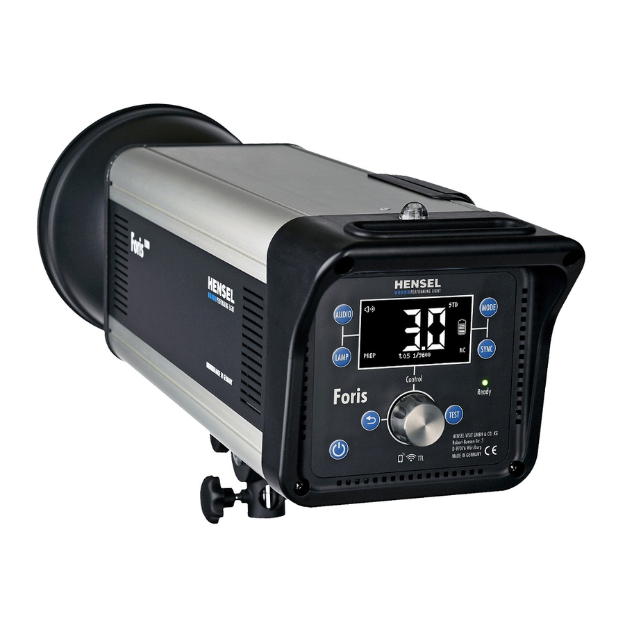
- Page 1 Compact flash Foris 1000 User manual Translation of the original German user manual Doc. no. 900.0520.00 Version: 1/2020...
-
Page 2: Table Of Contents
Contents Information about this manual and about the manufacturer ....5 Keeping this manual on hand ..............5 Design features in the text ..............5 Design features in the figures ..............6 Copyright ....................6 Manufacturer’s address ................6 Safety ......................7 Intended use .................... - Page 3 Mounting the device on/removing it from a stand ....... 34 Rotating and tilting the device .............. 36 Mounting the device on/removing it from a pantograph ..... 38 Mounting the umbrella on/removing it from the device ...... 41 Operating the device ................43 Activating and deactivating the device ..........
- Page 4 Outside of Germany ................65 Documents....................66 EU Declaration of Conformity ..............66 UN certificate for the rechargeable battery .......... 66 Accessories ..................... 67 Rechargeable battery ................67 Protection glass ..................67 Flash tubes ..................... 67 Radio remote trigger ................67 Light shaping tools .................
-
Page 5: Information About This Manual And About The Manufacturer
Information about this manual and about the manufacturer This manual can assist you with safe use of the “Foris 1000” compact flash. The “Foris 1000” compact flash is called “device” for short in the following text. Keeping this manual on hand This manual is part of the device. -
Page 6: Design Features In The Figures
Copyright This manual contains information that is subject to copyright. Without the prior written permission of Hensel-Visit GmbH & Co. KG, this manual shall not be copied, printed, filmed, processed, reproduced or distributed in any form, in full or in excerpts. -
Page 7: Safety
Safety Safety The device has been built according to state-of-the-art technology and recognized safety-related regulations. During work with and on the device, however, residual risk remains, which could present a danger to life and limb. For this reason, the following safety information is to be observed and followed. - Page 8 Safety Check the device annually for operating safety (see the maintenance schedule on page 57). Regularly clean the outside of the device with a dry cloth. Have damaged cables and the device replaced immediately by the authorized Customer Service only. Prevention of serious injuries due to fire When the flash tube is triggered, sparks might arise, which could lead to fire.
-
Page 9: Prevention Of Equipment Damage And Malfunctions
Safety Prevention of the risk of burns Heat is generated during the operation of the device. This heat can heat up the flash tube, model light, protection glass and light shaping tool, resulting in burns in case of contact with the skin. ... - Page 10 Safety Prevention of equipment damage when using external products The use of the device in combination with external products can lead to equipment damage. Use the device only with accessories and original spare parts recommended by the manufacturer. Malfunctions due to electromagnetic radio signals The device transmits and receives electromagnetic radiation in a frequency range from 2.3995 to 2.4745 GHz according to IEEE 802.11 n.
-
Page 11: Design Features Of Warning Notices
Safety Design features of warning notices This user manual contains the following safety information: DANGER Notices with the word DANGER warn about a dangerous situation that could lead to death or serious injuries. WARNING Messages with the word WARNING warn about a dangerous situation that could lead to death or serious injuries. -
Page 12: Warning And Information Sign
Safety Warning and information sign Explanation Remove the transport cap before commissioning... -
Page 13: Description
Description Description Overview of scope of delivery Designation Device Protection glass (packed separately) Standard charger (not shown) -
Page 14: Overview Of Device
Description Overview of device Designation Handle Protection glass Transport cap Flash tube Lock of the holder for the light shaping tool and transport cap Swivel head Rechargeable battery compartment... -
Page 15: Overview Of Interfaces To Other Devices
Description Overview of interfaces to other devices Designation Photo cell Sync socket (not shown) USB port (not shown) The sync socket and USB port can be found on the bottom of the user panel. -
Page 16: Overview Of Swivel Head
Description Overview of swivel head Designation Umbrella holder Locking lever Hanger clip for safety rope Thread for locking screw Knurled screw for stand adapter Knurled screw for umbrella holder... -
Page 17: Overview Of Controls
Description Overview of controls Designation Display MODE button: Select operating modes Open “Mode” submenu SYNC button: Activate and deactivate photo cell and radio receiver Open “Sync” submenu Ready: LED, lights up at flash readiness TEST button: Trigger a flash Rotary switch for setting the flash energy or for opening the main menu and selecting and setting the parameters in the menus... -
Page 18: Leds And Controls On Rechargeable Battery
Description Designation Back button: Go back a menu level Power button LAMP button: Activate and deactivate the model light in “Full” and “Prop” modes Open “Lamp” submenu AUDIO button: Signal tone for activation and deactivation of flash readiness Open “Audio” submenu LEDs and controls on rechargeable battery Designation Red: Rechargeable battery charged to 30% (low) -
Page 19: Task And Function
Description Task and function The device is used for illuminating photographs indoors. It can be used on a stand or pantograph. The device can be used in the following operating modes: STD (Standard) FREEZE FP (Focal Plane) ... - Page 20 Description reduction. After a preset time of 35 minutes, the brightness is dimmed to half (level 9) in “Full” mode. In “Prop” mode, the brightness is reduced to half when the flash energy is set in a range from 9.1 to 10. Synchronization with the camera takes place using either a sync cord, the built-in photo cell or the built-in radio receiver.
-
Page 21: Type Plate
Description Type plate The type plate is attached to the housing. You will find the following information on the type plate: Manufacturer name Name of the model Code number CE marking Symbol for environmentally sound disposal ... -
Page 22: Technical Data
Description Technical data Device type Foris 1000 Article number 8400 Energy (Ws) 1,000 Guide number STD mode 90 6/10 Flash durations 1/10,000–1/1,000 s (t0.5) STD mode 1/50,000–1/1,800 s (t0.5) FREEZE mode 1/400–1/240 s (t0.5) FP mode 1/120 (t0,1) Flash recycling time STD mode 0.08 s–2.44 s (1.6 s at 500 Ws) - Page 23 Description Device type Foris 1000 Charging duration 3.5 h with standard charger 1 h with optional quick charger Connection for light shaping Quickexchange system for EH (10 cm) tool Additional features Radio remote control with optional Hensel IO TTL transmitter TTL control and short time synchronization “FP mode”...
- Page 24 Description Device type Rechargeable battery Capacity 93.6 Wh Nominal rechargeable battery 36 V voltage L x W x H in mm 14.0 x 8.7 x 9.0 mm Weight 738 g...
-
Page 25: Unpacking The Device And Checking The Scope Of Delivery
Unpacking the device and checking the scope of delivery Unpacking the device and checking the scope of delivery Remove the product from the packaging. Keep the original packaging in case you need to return the product to Customer Service. ... -
Page 26: Commissioning The Device
Commissioning the device Commissioning the device To commission the device, proceed as follows: Remove the transport cap (see page 27). Position the protection glass in place (see page 29). Mount the light shaping tool (see page 31). ... -
Page 27: Mounting And Removing Components Of The Device
Mounting and removing components of the device Mounting and removing components of the device IMPORTANT! The device can be damaged if external products are used. Use only original spare parts and accessories from the manufacturer. Removing and installing the transport cap WARNING Heat is generated during the operation of the device, which can lead to a fire if the transport cap is in place. - Page 28 Mounting and removing components of the device To install the transport cap, proceed as follows: Press the lock (1) against the spring force to the limit stop. Place the transport cap (3) on the device in such a manner that the three mounting claws (2) are inside the transport cap (3) and engage in the openings.
-
Page 29: Installing And Removing The Protection Glass
Mounting and removing components of the device Installing and removing the protection glass WARNING Heat is generated during the operation of the device. Touching the device at the front can lead to severe burns. Always let the device cool down for 5 to 10 minutes before mounting or removing components. - Page 30 Mounting and removing components of the device To remove the protection glass (1), proceed as follows: Tilt the protection glass (1) slightly and so that it disengages from two of the three springs (2) one after the other. Release the protection glass (1) from the third spring (2) by pulling it slightly and remove it.
-
Page 31: Mounting The Light Shaping Tool On/Removing It From The Device
Mounting and removing components of the device Mounting the light shaping tool on/removing it from the device WARNING Heat is generated during the operation of the device. Touching the device at the front can lead to severe burns. Always let the device cool down for 5 to 10 minutes before mounting or removing components. - Page 32 Mounting and removing components of the device To mount the light shaping tool onto the device, proceed as follows: Press the lock (1) against the spring force to the limit stop. Place the light shaping tool (3) on the device in such a manner that the three mounting claws (2) are inside the light shaping tool (3).
- Page 33 Mounting and removing components of the device To remove the light shaping tool, proceed as follows: Hold the light shaping tool (3) firmly in one hand. With the other hand, press the lock (1) against the spring force to the limit stop.
-
Page 34: Mounting The Device On/Removing It From A Stand
Mounting and removing components of the device Mounting the device on/removing it from a stand To mount the device on a stand, proceed as follows: Loosen the knurled screw (1). Make sure that you do not completely unscrew the knurled screw (1). ... - Page 35 Mounting and removing components of the device To remove the device from the stand, proceed as follows: Loosen the knurled screw (1). Remove the device from the stand (2).
-
Page 36: Rotating And Tilting The Device
Mounting and removing components of the device Rotating and tilting the device CAUTION Crushing injuries can occur when loosening the locking lever. To prevent twisting and tipping over, hold the device firmly with one hand while loosening the locking lever with the other. - Page 37 Mounting and removing components of the device To tilt the device vertically, loosen the locking lever (2). Pivot the device into the desired position and tighten the locking lever (2).
-
Page 38: Mounting The Device On/Removing It From A Pantograph
Mounting and removing components of the device Mounting the device on/removing it from a pantograph WARNING In the case of a device attached to a pantograph, the anchorage can loosen and the device can fall, leading to injuries. Secure the device with an additional locking screw (M6 x 16). - Page 39 Mounting and removing components of the device Guide the safety rope (4) through a suitable and stable opening in the stay arm as seen in the following figure. Open the screw hook (7). Insert the rope thimble (6) into the screw hook (7). ...
- Page 40 Mounting and removing components of the device To remove the device, proceed as follows: Open the screw hook (7). Remove the screw hook (7) from the hanger clip (5). Remove the rope thimble (6) from the screw hook (7). ...
-
Page 41: Mounting The Umbrella On/Removing It From The Device
Mounting and removing components of the device Mounting the umbrella on/removing it from the device To mount the umbrella on the device, proceed as follows: Loosen the knurled screw (2). Make sure that you do not completely unscrew the knurled screw (2). ... - Page 42 Mounting and removing components of the device To remove the umbrella, proceed as follows: Hold the umbrella firmly with one hand. Loosen the knurled screw (2). Make sure that you do not completely unscrew the knurled screw (2). ...
-
Page 43: Operating The Device
Operating the device Operating the device Activating and deactivating the device To turn on the device, press and hold the power button. To turn off the device, press and hold the power button again. Triggering a test flash To trigger a test flash, proceed as follows: ... -
Page 44: Making Settings On The Device Or In The Menus
Operating the device Making settings on the device or in the menus To make settings in the menus, proceed as follows: Make sure the device is switched on. Press the rotary switch once and keep it pressed. The main menu is displayed: “Audio”... -
Page 45: Activating And Deactivating The "Audio" Function
Operating the device Activating and deactivating the “Audio” function With the “Audio” function, flash readiness after charging or after a reduction of the flash energy is indicated by an acoustic tone. To activate the “Audio” function, proceed as follows: Briefly press the AUDIO button. The signal tone for flash readiness is switched on. -
Page 46: Making Settings In The "Audio" Submenu
Operating the device Making settings in the “Audio” submenu To make settings in the “Audio” submenu, proceed as follows: Use the rotary switch to highlight the “Audio” menu item in the main menu. Briefly press the rotary switch once. The last values set are displayed: Sound Activation: ON: Signal tone activated... -
Page 47: Activating And Deactivating The Model Light
Operating the device Activating and deactivating the model light “Full” mode To activate the model light in “Full” mode, proceed as follows: Briefly press the LAMP button. The display shows “Full”. The model light lights up with maximum brightness, irrespective of the set flash energy. To deactivate the model light in “Full”... -
Page 48: Making Settings In The "Lamp" Submenu
Operating the device Making settings in the “Lamp” submenu To make settings in the “Lamp” submenu, proceed as follows: Use the rotary switch to highlight the “Lamp” menu item in the main menu. Briefly press the rotary switch once. The “Lamp”... -
Page 49: Checking The Function Of The Model Lamp
Operating the device Use the rotary switch to select “ON” or “OFF”. Briefly press the rotary switch once. The corresponding value is saved. To activate the time for the model light reduction (Autored), proceed as follows: Use the rotary switch to highlight the “Autored Time Min” menu item. ... -
Page 50: Activating And Deactivating The Led Model Light (Lamp Boost)
Operating the device Activating and deactivating the LED model light (Lamp Boost) To activate the “Lamp Boost” LED model light, proceed as follows: Briefly press the rotary switch once. The model light is switched to double energy for 30 seconds. To deactivate the “Lamp Boost”... - Page 51 Operating the device To activate and deactivate the photo cell, proceed as follows: Briefly press the SYNC button. The photo cell is activated. Press the SYNC button again three times. The photo cell is deactivated. Alternatively, you can switch the photo cell on and off in the “Sync” submenu.
-
Page 52: Making Settings In The "Sync" Submenu
Operating the device Making settings in the “Sync” submenu To make settings in the “Sync” submenu, proceed as follows: Use the rotary switch to highlight the “Sync” menu item in the main menu. Briefly press the rotary switch once. The last values set are displayed: Radio: Activate and deactivate the radio... -
Page 53: Selecting Operating Modes
Operating the device Proceed in the same way when setting the channel. Observe and follow the instructions of the radio remote trigger. To exit the “Sync” submenu, press the Back button. Selecting operating modes To select the operating modes, proceed as follows: ... -
Page 54: Making Settings In The "Mode" Submenu
Operating the device Making settings in the “Mode” submenu To make settings in the “Mode” submenu, proceed as follows: Use the rotary switch to highlight the “Mode” menu item in the main menu Briefly press the rotary switch once. The last values set are displayed: Mode: Set STD, FREEZE, FP or TTL mode... -
Page 55: Error Messages
Error messages Error messages Problem Possible causes Remedy Keep the device Hot temperature error – High ambient the model light turns off, temperature at full switched on so that the fan runs at model light, unsuitable the fan can cool down maximum speed and the light shaping tools, the device. -
Page 56: Transporting And Storing The Device
Transporting and storing the device Transporting and storing the device To transport and store the device, proceed as follows: Remove the light shaping tool (see page 31). Position the transport cap in place (see page 27). Remove the rechargeable battery from the device (see page 62). ... -
Page 57: Servicing The Device
Servicing the device Servicing the device Caring for and cleaning the device WARNING Heat is generated during the operation of the device. Touching the device at the front can lead to severe burns. Let the device cool down for 5 to 15 minutes before cleaning. -
Page 58: Replacing A Defective Protection Glass
Servicing the device Replacing a defective protection glass WARNING Heat is generated during the operation of the device. Touching the device at the front can lead to severe burns. Always let the device cool down for 5 to 10 minutes before mounting or removing components. -
Page 59: Replacing A Defective Flash Tube
Servicing the device Replacing a defective flash tube DANGER In the case of a defective flash tube, the electrodes are exposed. Touching the flash tube may result in an electric shock. Switch off the device. Disconnect the device from the power supply or remove the rechargeable battery. - Page 60 Servicing the device Pull out the flash tube (3). If necessary, remove all glass fragments of the flash tube. Remove the new flash tube from the packaging. Make sure the glass body of the new flash tube is not defective. ...
- Page 61 Servicing the device If the trigger wire is too loosely wrapped around the connection pin or not at all, the flash function may fail. If the trigger wire is not bent towards the glass body of the flash tube, the trigger voltage flows off through the protective conductor of the device and the device does not release a flash.
-
Page 62: Charging The Rechargeable Battery
Servicing the device Charging the rechargeable battery Depending on the operating conditions and the flash energy setting, the rechargeable battery has an approximate capacity of: 300 flashes at 1000 Ws 600 flashes at 500 Ws 1200 flashes at 250 Ws, etc. To charge the rechargeable battery, proceed as follows: ... -
Page 63: Putting The Rechargeable Battery In "Storage" Mode
Servicing the device If you use the charger included in the scope of delivery, the charging time is 3.5 hours. If you use the optional quick charger, the charging time is 1 hour. After charging, proceed as follows: Pull up the lock on the rechargeable battery and insert the rechargeable battery into the battery compartment again. -
Page 64: Performing Firmware Updates
Performing firmware updates Performing firmware updates The firmware version of the device can be updated over the USB port. For more information, contact Customer Service. -
Page 65: Disposing Of The Device And Packaging
Disposing of the device and packaging Disposing of the device and packaging In Germany Dispose of the packaging of the device, separated according to material. Use local options for collecting paper, cardboard and lightweight packaging. Dispose of the device and accessories separately from domestic waste. Information regarding collection points that accept old devices free of charge can be obtained from your municipal authority. -
Page 66: Documents
Documents Documents EU Declaration of Conformity Hensel-Visit GmbH & Co. KG hereby declares that device type “Foris 1000” corresponds with Directive 2014/53/EU. The complete text of the EU Declaration of Conformity is available under the following URL https://support.hensel.eu/index.php/eu-konformitaetserklaerungen. UN certificate for the rechargeable battery The UN certificate for the harmlessness of the battery during transport is available at the following Internet address in the category “Harmlessness... -
Page 67: Accessories
Accessories Accessories Rechargeable battery Designation Article number Rechargeable battery for Foris 1000 8900 Protection glass Designation Article number Transparent, uncoated, frosted 9454659 Flash tubes Designation Article number Plug-in style, single coating 99150052 Radio remote trigger Designation Article number IO TTL transmitter for Canon cameras... -
Page 68: Charger
Accessories Charger Designation Article number Quick charger (optional) 1696 Additional accessories Designation Article number Safety rope 7690 Information on additional accessories can be found on our website. -
Page 69: Warranty Provisions
Warranty provisions Warranty provisions In Germany The warranty provisions can be found in our general terms and conditions for business on our website: www.hensel.de Outside of Germany The warranty provisions of the dealer from which you have purchased the device apply. -
Page 70: Limitation Of Liability
Limitation of liability Limitation of liability We are not liable for equipment or property damage, or personal injury arising from improper use of the device that is inconsistent with the information provided in the user manual. We are also not liable for consequential damages (such as production or income losses, etc.) that may be caused by a defect in or malfunction of our device. -
Page 71: Returning A Product To Customer Service
As soon as you discover damage to the device, proceed as follows: Send the device in its original packaging with a precise description of the defect to the following address for repair: HENSEL-VISIT GmbH & Co. KG Customer Service Department Robert-Bunsen-Str. 3 D-97076 Würzburg, Germany...
Need help?
Do you have a question about the Foris 1000 and is the answer not in the manual?
Questions and answers