Table of Contents
Advertisement
Quick Links
OPERATIONS AND MAINTENANCE MANUAL
BAKER ATLAS 5715XA PANEL
SECTION
1.0
2.0
3.0
4.0
5.0
6.0
7.0
8.0
9.0
AMS4A040 PANEL USER MANUAL Rev H Nov 2006
WINCH OPERATORS PANEL
F140529000
Kerr p/n AMS4A040
TABLE OF CONTENTS
DESCRIPTION
GENERAL DESCRIPTION
DETAILED DESCRIPTION OF FEATURES
MENU OPERATING INSTRUCTIONS
OPEN HOLE MODE
MENU OPERATING INSTRUCTIONS
CASED HOLE MODE
SYSTEM OPERATING INSTRUCTIONS
DRAWINGS, SETUP PROCEDURES AND
PARTS LISTS
INSTALLING NEW SOFTWARE
CABLE DRAWINGS
CE TEST CERTIFICATES
Page 1 of 39
Advertisement
Table of Contents

Summary of Contents for Benchmark BAKER ATLAS 5715XA
- Page 1 OPERATIONS AND MAINTENANCE MANUAL WINCH OPERATORS PANEL BAKER ATLAS 5715XA PANEL F140529000 Kerr p/n AMS4A040 TABLE OF CONTENTS SECTION DESCRIPTION GENERAL DESCRIPTION DETAILED DESCRIPTION OF FEATURES MENU OPERATING INSTRUCTIONS OPEN HOLE MODE MENU OPERATING INSTRUCTIONS CASED HOLE MODE SYSTEM OPERATING INSTRUCTIONS...
-
Page 2: General Description
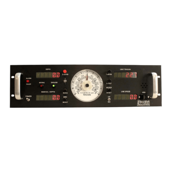
INTRODUCTION GENERAL DESCRIPTION This panel is designed to acquire and display depth, tension, and magnetic mark data from a wireline logging winch unit. The panel provides the operator a means to set and make adjustments to the data as necessary. Depth is displayed from data provided from an encoder mounted on a measuring device. -
Page 3: Features And Specifications
FEATURES AND SPECIFICATIONS Digital displays for depth, line speed, tension and magnetic marks (or CCL offset) Analog incremental tension meter, 4 inch (108 mm) dia., 270 degree Differential or Incremental tension zero push button switch Excessive tension alarm setting allows operator to set tension alarm to a predetermined value. - Page 4 2.0 DETAILED DESCRIPTION OF FEATURES FRONT PANEL 2.1.1 ANALOG TENSION METER This meter displays either differential or incremental tension. This provides a more visual display of tension change. 2.1.2 INCREMENTAL/TOTAL TENSION SWITCH This switch will change the analog meter from Incremental tension to Differential tension.
-
Page 5: English / Metric Units
2.1.8 MAGNETIC MARK RESET Pressing the MMD reset button clears the last mark setting. The next mark detected will be used to set the window for any subsequent marks. 2.1.9 ZERO DEPTH Pressing this button will reset the depth to 0. Depressing the button again will reset the depth to the previous setting. - Page 6 2.1.14 T-ZERO SWITCH Use this switch to set the tension to 0 at the start of a logging run. This will zero out the tension circuit. The line should be slack through the head at this time. 2.1.15 T-TEST SWITCH Press T-TEST and verify that the panel tension reads 20000 lbs (MODE 5) or 5000 lbs (MODE 3).
-
Page 7: Jumper Settings
JUMPER SETTINGS A row of jumpers are located on the internal processor board to set the panel in different configurations. J1 on = DEPTH IN METERS J1 off = DEPTH IN FEET J2 on = TENSION IN KG J2 off = TENSION IN POUNDS J3 on = CASED HOLE MODE (AM3K + CASE OR HOIST) J3 off = OPEN HOLE MODE (AM5K + FOCUS) J4 off = Rev D or earlier PC board... -
Page 8: Cable Size
3.0 MENU COMMANDS – OPEN HOLE MODE This panel has internal software which allows it to be set for various configurations. To change the settings, press the MENU button. The feature to be set will be displayed on the DEPTH display. Press the MENU button again until the feature you want to set is displayed. - Page 9 S-SLAM Other Default value is 7-16 If OTHER is selected, two additional options are available. LCA and WHLCIR. LCA (Load Cell Angle). This setting allows for the use of a sheave mounted load cell. The angle of the cable exiting the sheave should be entered.
- Page 10 TENSION SHUTDOWN Functionality: When value is reached, alarm sounds, tension display flashes value, and tension contact closure switch is closed. This can be used to provide a signal to automatically stop the winch. Procedure: Use +/- switch to set tension shutdown setting Indication: TSHTDN will be displayed on the DEPTH display and the value will be displayed on the TENSION display as it is being...
-
Page 11: Depth Alarm
DELTA TENSION SHUTDOWN Functionality: When value is reached, alarm sounds, tension display flashes value, and tension contact closure switch is closed. This can be used to provide a signal to automatically stop the winch. Procedure: Use +/- switch to set tension shutdown setting Indication: DTSHDN will be displayed on the DEPTH display and the value will be displayed on the TENSION display as it is being... - Page 12 Functionality: The MMD window determines when the next mark can be detected. The cable must travel at least the distance of the value set before a mark can be detected. Marks can only be detected if they occur within this window. I.E. If the window is set for 95', the cable must travel 95' from the last mark before a new mark can be detected.
-
Page 13: Encoder Direction
3.11 ENCODER DIRECTION Functionality: The value selected will toggle the encoder direction between UP and Down. Procedure: Use +/- switch to set the ENCODER direction setting. Indication: ENCDIR will be displayed on the DEPTH display and either UP or DN value will be displayed on the TENSION display. Default value is UP. - Page 14 4.0 MENU COMMANDS – CASED HOLE MODE In this mode (cased hole) the panel is configured to work with the AM3K measuring head and the Baker Atlas CASE and HOIST acquisition systems. Jumper J3 must be installed to put the system in this mode (refer to section 2.3). LOGGING SYSTEM TYPE Functionality: This setting determines the encoder pulse rate that will be output to the acquisition system.
- Page 15 Indication: CABLE will be displayed on the DEPTH display and the selections will be displayed on the LINE TENSION display. Cable Size Values available 7-32 9-32 5-16 (Default setting) Other TENSION ALARM Functionality: When preset tension value is reached, alarm sounds and tension display flashes value Procedure: Use +/- switch to set the tension alarm setting.
- Page 16 TENSION SHUTDOWN This value is added to the DTALRM or the TALRM settings to determine when the shutdown relay is activated. Example: If the TNALRM is set to 4000 and the TSHTDN is set to 500, the ALARM will sound when tension reaches 4000lbs and the OT contacts will close when tension reaches 4500lbs If the Tension Alarm is set to 2000 and the Shutdown is set to 150 then the winch shutdown will occur at 2150 lbs.
- Page 17 Procedure: Use +/- switch to set the CCL offset depth Indication: CCL will be displayed on the DEPTH display and the value will be displayed on the TENSION display as it is being set. DEPTH ADJUST (Shim) Functionality: The shim amount selected will automatically be added or subtracted from the depth input.
- Page 18 5.0 SYSTEM OPERATING INSTRUCTIONS Power up panel and verify it is working properly. Verify the panel is configured to match the system (head type, Acquisition System, encoder, etc.) Set up acquisition system: Press T-Zero and verify that panel tension reads 0. Verify tension is recorded on acquisition system.
-
Page 19: Drawings And Parts Lists
6.0 DRAWINGS AND PARTS LISTS 6.1 Main Processor Board AMS4A040 PANEL USER MANUAL Rev H Nov 2006 Page 19 of 39... - Page 20 6.1.1 ENCODER AND MMD INPUTS AMS4A040 PANEL USER MANUAL Rev H Nov 2006 Page 20 of 39...
- Page 21 6.1.2 ENCODER OUTPUT AND COM PORT I/O AMS4A040 PANEL USER MANUAL Rev H Nov 2006 Page 21 of 39...
- Page 22 6.1.3 LOAD PIN AND TENSION I/O AMS4A040 PANEL USER MANUAL Rev H Nov 2006 Page 22 of 39...
- Page 23 6.1.4 JUMPERS – BUTTONS AMS4A040 PANEL USER MANUAL Rev H Nov 2006 Page 23 of 39...
- Page 24 6.1.5 POWER SUPPLIES AMS4A040 PANEL USER MANUAL Rev H Nov 2006 Page 24 of 39...
- Page 25 6.2 Wire List AMS 4A040 WIRING LIST-- REV L P2 - Screw Terminal Block P1-7 P2 -1 BATT + (FUSE SWITCHED POWER BRD) P2 -2 BATT - BLK - B J1 B CONTACT Tension Contact Closure Back P2 -3 GRN - B J6 A CLOSURE N.O.
- Page 26 P6 - 4 LOAD PIN SIG- J2 22 LOAD PIN SIG- SHUNT CAL P6 - 7 J2 9 SHUNT CAL ENABLE P6 - 8 J2 21 GROUND P6 - 9 4to20OUT J5-12 4 to 20 mA to system P6 - 10 J5-21 TENSION OUT- TO SYSTEM 0-2V OUT...
- Page 27 APPROACHING P8 - 9 SW 10 +1 (inline with silver plate) SURFACE LED - APPROACHING P8 - 10 SW 10 -1 (opposite silver plate) SURFACE LED + P8 - 11 PHASE 1B* J5 15 Quadrature Out - PHASE B* P8 - 12 PHASE 1B J5 3 Quadrature Out - PHASE B...
- Page 28 D1 DISPLAY - MMD DEPTH (10 PIN) D1-2 D2 1 GND OUT D1-6 +5V OUT D2 4 POWER OUT D2 DISPLAY - DEPTH (10 PIN) D2-2 D3 1 GND OUT D2-6 +5V OUT D3 4 POWER OUT D3 DISPLAY - LINE TENSION (10 PIN) D3-2 D4 1 GND OUT...
- Page 29 6.3 FUSE BOARD AND POWER WIRING Refer to 5.2 for wirelist AMS4A040 PANEL USER MANUAL Rev H Nov 2006 Page 29 of 39...
-
Page 30: Digital Display Setup
DIGITAL DISPLAY SETUP The four digital displays can be set for address, baud rate, and brightness. The button nearest the connector selects the parameter (address, baud rate, brightness). The center button increments the parameter up The end button increments the parameter down. After the parameter is set, press the parameter button again to store it. - Page 31 J2-25 STRONG MARK + STRONG MARK IN - J3-1 CTS+ IN J3-2 CTS- IN J3-4 RS485RX+ RS485 RX+ (2 WIRES) J3-5 RS485RX- RS485 RX- (2 WIRES) J3-6 RTS+ IN J3-7 RTS- IN J3-8 RS485 TX+ RS485 TX+ (2 WIRES) J3-9 RS485 TX- RS485 TX- (2 WIRES) J4-1...
-
Page 32: Spare Parts List
6.6 SPARE PARTS LIST Part No. Description Qty Reference AMS4P133 PC BOARD AMS40 REV E W/2xRS232 1x485 MOTHER BOARD AMS4P110 METER ANALOG DIFF TENSION (+/- 1000 LBS) AMS4P120 DISPLAY LED .5" SERIAL 2"X3.5" D2, D3 ACMU1P06 LED RED DIALIGHT 5V APPROACHING SURF ACMU1P11 SONALERT #SC628D MALLORY ALARM... -
Page 33: Installing New Software
7.0 INSTALLING NEW SOFTWARE SOFTWARE MODIFICATION BY REPLACING THE EPROM The software that controls this panel is stored in an EPROM Integrated Circuit located at U2 (see drawing on next page). To upgrade the software to a new version, simply remove the eprom I.C. and install a new eprom I.C. (be careful not to bend the legs during installation). - Page 34 7.2.2 PROCEDURE: 1. Transfer the new revision HEX file to the computers (C:\) root directory. 2. Turn power on to the Hoistman’s panel. 3. Connect your PC to the serial port at the rear of the panel. 4. Open a Hyperterminal session. Use the following settings: Serial Port: COM1 Baud Rate: 57600 Data Bits: 8...
- Page 35 GGGGGGGGGGGGGGGGGGGGGGGGGGGGGGGGGGGGGGGGGGGGGGGGGG GGGGGGGGGGGGGGGGGGGGGGGGGGGGGGGGGGGGGGGGGGGGGGGGGG GGGGGGGGGGGGGGGGGGGGGGGGGGGGGGGGGGGGGGGGGGGGGGGGGG GGGGGGGGGGGGGGGGGGGGGGGGGGGGGGGGGGGGGGGGGGGGGGGGGG GGGGGGGGGGGGGGGGGGGGGGGGGGGGGGGGGGGGGGGGGGGGGGGGGG GGGGGGGGGGGGGGGGGGGGGGGGGGGGGGGGGGGGGGGGGGGGGGGGGG GGGGGGGGGGGGGGGGGGGGGGGGGGGGGGGGGGGGGGGGG 11. After the ROM Loader is finished programming the Flash set the switches on the CPU piggy-back PCB as follows: 1 - TOWARD CPU 2 - TOWARD CPU 3 - AWAY FROM CPU 12.
-
Page 36: Cable Diagrams
CABLE DIAGRAMS AMS7A022 CABLE ASSEMBLY – DC POWER IN A = + B = - Kerr p/n Description AMS7P061 CABLE 16-2 SJ CORD BELDEN 8472 AMS7P044 CONN MS3106E-14S-9S AMS7P063 BUSHING #9779-513-6 AMPHENOL AMS4A040 PANEL USER MANUAL Rev H Nov 2006 Page 36 of 39... - Page 37 LOGGING UNIT INTERFACE CABLE HARNESS AMS4A187 AMS4A040 PANEL USER MANUAL Rev H Nov 2006 Page 37 of 39...
- Page 38 9.0 CE TEST CERTIFICATE AMS4A040 PANEL USER MANUAL Rev H Nov 2006 Page 38 of 39...
- Page 39 AMS4A040 PANEL USER MANUAL Rev H Nov 2006 Page 39 of 39...
Need help?
Do you have a question about the BAKER ATLAS 5715XA and is the answer not in the manual?
Questions and answers