
Subscribe to Our Youtube Channel
Related Manuals for Campbell AM25T


Summary of Contents for Campbell AM25T
- Page 1 AM25T Solid-State Thermocouple Multiplexer Revision: 1/19 Copyright © 1995 – 2019 Campbell Scientific, Inc.
- Page 2 Limited Warranty “Products manufactured by CSI are warranted by CSI to be free from defects in materials and workmanship under normal use and service for twelve months from the date of shipment unless otherwise specified in the corresponding product manual. (Product manuals are available for review online at www.campbellsci.com.) Products not manufactured by CSI, but that are resold by CSI, are warranted only to the limits extended by the original manufacturer.
- Page 3 Campbell Scientific company serves your country. To obtain a Returned Materials Authorization (RMA) number, contact CAMPBELL SCIENTIFIC, INC., phone (435) 227-9000. Please write the issued RMA number clearly on the outside of the shipping container. Campbell Scientific’s shipping address is: CAMPBELL SCIENTIFIC, INC.
- Page 4 Periodically (at least yearly) check electrical ground connections. • WHILE EVERY ATTEMPT IS MADE TO EMBODY THE HIGHEST DEGREE OF SAFETY IN ALL CAMPBELL SCIENTIFIC PRODUCTS, THE CUSTOMER ASSUMES ALL RISK FROM ANY INJURY RESULTING FROM IMPROPER INSTALLATION, USE, OR MAINTENANCE OF TRIPODS, TOWERS, OR ATTACHMENTS TO TRIPODS AND TOWERS SUCH AS SENSORS, CROSSARMS, ENCLOSURES, ANTENNAS, ETC.
- Page 5 Clock (CLK) ..................3 5. Terminal Strips ............4 6. Specifications ............5 7. Installation ..............6 Installing the AM25T ................6 Data Logger to AM25T Wiring ............7 Sensor to AM25T Wiring ..............8 7.3.1 Thermocouple Measurement ............8 7.3.2 Differential Analog Measurements ..........9 7.3.3...
-
Page 6: Table Of Contents
Table of Contents B. Example Program ..........B-1 Figures 1-1. AM25T Solid-State Thermocouple Multiplexer ........1 5-1. AM25T Solid-State Thermocouple Multiplexer with Cover (Screw Terminal Strips) ................4 5-2. AM25T with Spring-Loaded Terminals ..........5 7-1. External Battery Connections ...............7 7-2. Differential Measurement of Type T Thermocouple ......9 7-3. -
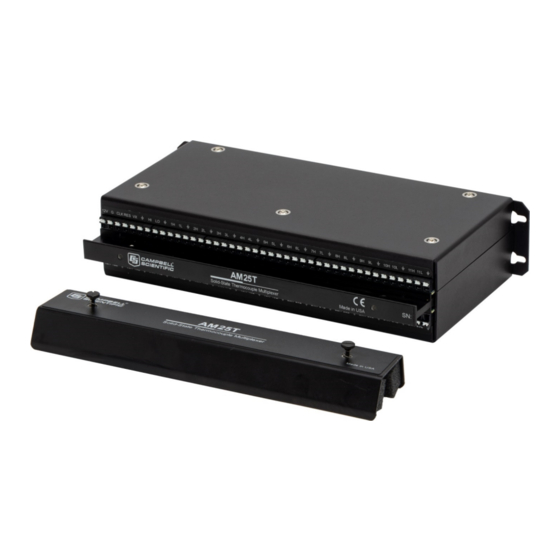
Page 7: Am25T Solid-State Thermocouple Multiplexer
The AM25T (FIGURE 1-1) multiplexer increases the number of channels for measuring thermocouples or voltage sensors with Campbell Scientific data loggers. The AM25T is positioned between the sensors and the data logger. The data logger controls the AM25T solid-state relays, sequentially connecting each sensor to the data logger. - Page 8 Campbell Scientific immediately if there are any discrepancies. Overview The AM25T is connected to the data logger with eight insulated wires and a large ground wire. These wires are used to power and control the multiplexer, and connect the common analog inputs to the data logger.
- Page 9 TABLE 7-1. Reset (RES) A control terminal is used to operate the RES channel. The AM25T is reset and activated by applying and holding 5 Vdc to the RES channel. Once the AM25T is activated, the AM25T reference temperature can be immediately measured.
-
Page 10: Am25T Solid-State Thermocouple Multiplexer With Cover
AM25T Solid-State Thermocouple Multiplexer Terminal Strips The AM25T is housed in an anodized aluminum case with a cover that helps reduce temperature gradients across the terminal strips (FIGURE 5-1). FIGURE 5-1. AM25T Solid-State Thermocouple Multiplexer with Cover (Screw Terminal Strips) The terminal strips that run the length of the AM25T are for sensor connections. -
Page 11: Am25T With Spring-Loaded Terminals
AM25T Solid-State Thermocouple Multiplexer FIGURE 5-2. AM25T with Spring-Loaded Terminals As shown in FIGURE 5-1, AM25T multiplexers prior to serial number 10147 will have screw terminals for each wire. To attach a wire, loosen the screw to widen the terminal gap, insert the wire, then tighten the screw. - Page 12 Campbell Scientific offers weather- resistant enclosures for this purpose. Fasten the AM25T to the enclosure backplate. Securely fasten the wires to the strain relief flange running between the AM25T terminal strips and install the...
-
Page 13: External Battery Connections
Damage to the multiplexer, sensors, and data logger will occur. A separate battery can be used to power the AM25T. A separate battery might be used when the AM25T is installed some distance from the data logger. Ground must be connected between the data logger and the AM25T (FIGURE 7-1). -
Page 14: Am25T To Data Logger Wiring
For example, a one-degree gradient between input terminals and the PRT will result in a one-degree measurement error. The thermal bar in the AM25T, which includes the strain relief, and the AM25T cover are designed to reduce gradients. The PRT is attached to the thermal bar. -
Page 15: Differential Measurement Of Type T Thermocouple
Shield Analog Ground Shield Analog Ground is the ⏚ terminal between VX and HI on the AM25T. Analog Ground is the terminal between VX and Hi on the AM25T FIGURE 7-2. Differential Measurement of Type T Thermocouple 7.3.2 Differential Analog Measurements Connect one differential sensor to a differential AM25T input channel. -
Page 16: Short Cut
AM25T Solid-State Thermocouple Multiplexer recommends use of Teflon®, polyethylene, or polypropylene insulation around individual conductors. Do not use PVC as conductor insulation. PVC may be used as a cable jacket. With long wire lengths, a delay within the measurement instruction will allow the capacitance of the lead wires to discharge before the measurement is made. - Page 17 In CRBasic, the AM25T() instruction is used to control the AM25T multiplexer with the data logger. The instruction measures the PRT incorporated in the AM25T and uses it as a reference temperature for thermocouple measurements. The AM25T() instruction and parameters are as...
- Page 18 Appendix A. Importing Short Cut Code Into CRBasic Editor This tutorial shows: Importing a Short Cut program into a program editor for additional • refinement Importing a wiring diagram from Short Cut into the comments of a • custom program Short Cut creates files, which can be imported into CRBasic Editor.
- Page 19 Appendix B. Example Program In this example, 25 type T thermocouples are connected to the AM25T. One AM25T() instruction will measure the AM25T PRT and the thermocouples. This program is written for the CR6 datalogger. Other CRBasic data loggers are programmed similarly. TABLE shows the wiring used with the example.
- Page 20 'Main Scan Scan(5,Sec,0,0) 'Default CR6 Datalogger Battery Voltage measurement 'BattV' Battery(BattV) 'Default CR6 Datalogger Wiring Panel Temperature measurement 'PTemp_C' PanelTemp(PTemp_C,60) 'Type T (copper-constantan) Thermocouple measurements 'Temp_C()' on the AM25T Multiplexer AM25T(Temp_C(),25,mv200C,1,U5,TypeT,RTempC,U1,U2,U3,True,0,60,1,0) 'Call Data Tables and Store Data CallTable Dat15sec CallTable...
- Page 21 Campbell Scientific Worldwide Offices Australia Germany Location: Garbutt, QLD Australia Location: Bremen, Germany Email: Email: info@campbellsci.com.au info@campbellsci.de Website: www.campbellsci.com.au Website: www.campbellsci.de Brazil South Africa Location: São Paulo, SP Brazil Location: Stellenbosch, South Africa Email: andread@campbellsci.com.br Email: sales@csafrica.co.za Website: Website: www.campbellsci.com.br www.campbellscientific.co.za...
Need help?
Do you have a question about the AM25T and is the answer not in the manual?
Questions and answers