
Summary of Contents for Plasson PFS Monomatic
- Page 1 Monomatic Monomatic Data USB Monomatic (Bluetooth) Monomatic Data USB (Bluetooth) SmartFuse electrofusion control unit SmartFuse electrofusion control unit with Bluetooth functionality...
- Page 2 EN001 H01...
-
Page 3: Table Of Contents
Table of contents Safety ....................5 General safety guidelines for power tools ............5 Specific safety guidelines for the electrofusion control unit ......6 Introduction ..................8 Scope of application ..................... 8 Maintenance and service ..................9 Handling and maintenance ................... 9 Disposal ......................... - Page 4 11.5.1 Connection of a fitting ................... 30 11.5.2 Starting the welding procedure with SmartFuse ............ 31 11.5.3 During the welding procedure ................33 11.5.4 After the end of the welding procedure ..............33 Function menu ................. 35 12.1 Using the letter field to enter data ..............36 12.2 Job no.* ........................
-
Page 5: Safety
1. Safety The basic condition for safely handling and a hassle-free operation of the product is the knowledge about the fundamental safety guidelines and safety regulations. This instruction manual contains important information about the safe operation and handling of the electrofusion control unit. Everyone working with electrofusion control unit shall read and understand these instructions. -
Page 6: Specific Safety Guidelines For The Electrofusion Control Unit
4) Personal safety a) Stay alert! Watch what you are doing and use common sense when operating an electrofusion control unit. Do not use an electrofusion control unit while being tired or under the influence of drugs, alcohol or medication. One moment of inattention while operating an electrofusion control unit can cause serious personal injury. - Page 7 d) Before each use, the user must visually inspect that the electrofusion control unit, its cables and accessories as well as its electrical supply cord to ensure that all parts are free from damage correctly installed. Damaged protection facilities and device parts must be repaired or replaced by an authorized service agent.
-
Page 8: Introduction
2. Introduction Different variants of the electrofusion control unit This instruction manual describes several different variants of the electrofusion control unit. These variants differ in the range of available functions and in the number of menu entries. The differences are pointed out where necessary. Please check which variant you have. 2.1 Scope of application The electrofusion control units of type Monomatic (Bluetooth) and Monomatic Data USB (Bluetooth) are solely meant for the welding of thermoplastic pipes (e.g. -
Page 9: Maintenance And Service
2.2 Maintenance and service Should the electrofusion control unit fail despite the great care taken in manufacturing and testing it, the necessary repairs should only be carried out by an after-sales service centre authorised by the manufacturer. Please note that the product is a technically demanding machine for field application. In accordance to the applicable standards like DVS 2208-1, BGV A3, ISO 12176-2 and most national and international standards, these machines are subject to a periodical maintenance. -
Page 10: Input Of Welding Parameters
3. Input of welding parameters The electrofusion control units of type Monomatic, Monomatic (Bluetooth), Monomatic Data USB and Monomatic Data USB (Bluetooth) provide the following means for entering the welding parameters: 3.1 SmartFuse-System By reading out the reference resistor in one of the connector pins of the SmartFuse-fitting the control unit automatically determines the welding parameters for the fitting. -
Page 11: Range Of Fitting Dimensions
5. Range of fitting dimensions The range of fitting dimensions for which an electrofusion control unit can be used depends essentially on the power consumption of the used fittings. Since the power consumption of the fittings is different for different fitting manufacturers, it is not possible to provide a general rule which covers all the possible fitting dimensions. -
Page 12: Technical Data
7. Technical data Monomatic / Monomatic (Bluetooth) Monomatic Data USB / Monomatic Data USB (Bluetooth) General Output voltage 40 AC Monomatic: No Monomatic (Bluetooth): No Data recording Monomatic Data USB: Yes Monomatic Data USB (Bluetooth): Yes Power (60 % ON time) 2050 W (55.9 A) according to ISO 12176-2 Operating temperature range... - Page 13 Input/Mains 230 V devices 110 V devices Nominal voltage (tolerance) 230 AC (190 to 300) 110 AC (90 to 150) Nominal frequency [Hz] 50/60 (40 to 70) 50/60 (40 to 70) (tolerance) 0.6 to 0.9 (phase-angle 0.6 to 0.9 (phase-angle Power factor cos ρ...
-
Page 14: Data Recording Monomatic
7.1 Data recording Monomatic The electrofusion control units of type Monomatic do not generate reports. 7.2 Data recording Monomatic (Bluetooth) When using the PFS app and the connection via Bluetooth, the electrofusion control units of type Monomatic (Bluetooth) transfer reports to the connected smartphone or tablet. An internal memory is not available in the electrofusion control unit. -
Page 15: Technical File According To Iso 12176-2
7.4 Technical file according to ISO 12176-2 Monomatic Monomatic (Bluetooth) Monomatic Data USB Monomatic Data USB (Bluetooth) Classification Monomatic / Monomatic (Bluetooth) Monomatic Device type Monomatic (Bluetooth) Classification 3 U S F A M Classification Monomatic Data USB / Monomatic Data USB (Bluetooth) Monomatic Data USB Device type Monomatic Data USB (Bluetooth) - Page 16 Duty cycle according to ISO 12176-2 at 30 %, 60 % and 100 %, Test time t = 60 minutes Test time Output power Output power Output current 60 min at U = 36 V at U = 40 V 30 % 2700 W 3000 W...
-
Page 17: Spare Parts And Accessories
8. Spare parts and accessories Description Code Welding Terminal 4.7mm, standard 1_0200_001 Welding Terminal 4.0mm, standard 1_0200_003 Welding terminal 4.7mm, Smart/Fuse (with detection tip) 2_0200_003 Welding terminal 4.0mm, Smart/Fuse (with detection tip) 2_0200_004 Universal terminal for 4.0 and 4.7 mm SmartFuse (with detection tip) 2_0200_051 Universal terminal for 4.0 and 4.7 mm, standard 2_0200_052... -
Page 18: Controls And Plugs
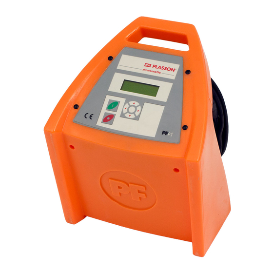
9. Controls and plugs ON-OFF-switch Display Arrow keys ▲ ▼ ◄ ► Welding cable Cable holder and carrying handle Enter button Mains supply cable Green start button USB interface Red stop button only: Monomatic Data USB and Monomatic Data USB (BT) EN001 H01... -
Page 19: Connection To The Power Supply
10. Connection to the power supply 10.1 General Attention! GERMANY: The conditions for connecting the electrofusion control unit in this instruction manual, the technical connection regulations of the local power supply company, the VDE regulations, the regulations for accident prevention as well as other DIN/CEN regulations in force must always be observed. -
Page 20: Extension Cables
10.2 Extension cables Attention! • The extension cords must provide a protective earthing contact. • It is forbidden to extend the welding cable. • Always observe all international and national legislation and guidelines for extending mains supply cords. 10.2.1 General The mains supply cord shall only be extended in accordance with the following specifications. -
Page 21: Generator Compatibility
10.3 Generator compatibility Important notes for the usage together with generators! • AUSTRALIA: Ensure that the generator is regularly inspected, tested and tagged by a licensed electrician or other competent person in accordance with workplace health and safety legislation and national Standards. •... -
Page 22: Required Generator Rated Output Power
10.3.1 Required generator rated output power Attention! It is not possible to make a statement for the necessary generator output power in each individual case, because every fitting manufacturer has different specifications. The information in the following table below is to be used only as a guide as it can differ from your actual requirements. -
Page 23: Starting A Welding Process
11. Starting a welding process The electrofusion control units Monomatic, Monomatic (Bluetooth), Monomatic Data USB and Monomatic Data USB (Bluetooth) only offer SmartFuse as a means for input of welding parameters. Attention! • The generator must be grounded! • If the electrofusion control unit is used on a generator which is not grounded or on mains without protective earthing conductor there is a risk of an electric shock. -
Page 24: Switching The Electrofusion Control Unit On
11.2 Switching the electrofusion control unit on 11.2.1 Monomatic (Bluetooth) Step Action Switch the ON-OFF-switch to "ON" position. The electrofusion control unit signals its readiness by two bleeps. The background lighting of the display turns on automatically. The display shows the following message for approx. 7 seconds: Monomatic BT 2.40H5 Display after switching on... -
Page 25: Other Display Messages
11.2.3 Other display messages After the startup display is shown, other messages might be displayed before the main display is shown. 11.2.3.1 System config. at last welding process If the system configuration is changed before the next restart of the electrofusion control unit, a message in the display is shown which indicates, that the system configuration has been changed and what was changed. -
Page 26: Pairing Via Bluetooth
11.3 Pairing via Bluetooth* Attention! The Bluetooth functionality is only available in electrofusion control units made by PF- Schweißtechnologie GmbH that are equipped with a Bluetooth module. In order to make the electrofusion control unit visible for your mobile device, the option "BT on" must be activated in the system configuration. -
Page 27: Option „Bt On" Active, „Bt Only" Active
11.3.2 Option „BT on“ active, „BT only“ active Step Action Display after switching on, if "BT on" and "BT only" are active The electrofusion control unit shows the following display. Now you can use the app to pair the electrofusion control unit with your mobile device. ↵Menu #10020981 Waiting for App... - Page 28 Step Action Display after pairing The electrofusion control unit shows the following display. ↵Menu #10020981 Waiting for App Display after proceeding in the app BT active Row 4 briefly shows the text "BT active". The electrofusion control unit indicates that it is operated by a mobile device.
-
Page 29: Main Display / Displaying Device Data
11.4 Main display / Displaying device data When the main display is shown you can display device data of the electrofusion control unit by pressing and holding the ► button. Step Action Before connecting a fitting, the display shows the main display: Connect SmartFuse Voltage: 230 V... -
Page 30: Welding With Smartfuse
11.5 Welding with SmartFuse Attention! The following description is based on the displays of an electrofusion control unit of type Monomatic Data USB (Bluetooth). 11.5.1 Connection of a fitting Attention! The contact surfaces of the welding terminals and the pins of the fitting must be clean. Dirty or coated terminals lead to overheating and scorching on the areas of contact inside the welding terminals. -
Page 31: Starting The Welding Procedure With Smartfuse
Step Action After the welding parameters have been determined, the electrofusion control unit shows the following information in the display: Start Nom. time: 30 s Display of the determined welding parameters PLA 40 V +20°C Row 1 indicates that you have to press the green start button to start the welding process. Before continuing you are obliged to cross check if the welding time, manufacturer, diameter and type are compliant to the connected fitting. - Page 32 Step Action Reminder After pressing the green start button a message will remind you of your duty to fix and prepare the pipes according to the general guidelines. If you have any doubt about the correct preparation, you can quit the procedure by actuating the red stop button. Otherwise, confirm that you prepared everything properly by pressing the green start button.
-
Page 33: During The Welding Procedure
11.5.3 During the welding procedure Step Action During the welding procedure The display shows the actual and nominal welding time: Act. time: Nom. time: 30 s Display during the welding procedure PLA 40 V Row 1 shows the actual welding time, which is counted upwards. Row 2 shows the nominal welding time. - Page 34 Step Action OPTIONAL: Display of weld-related data 12.1 After completion of the welding procedure, the following information of the welding can be displayed by keeping the ▲-button on the keypad pressed. 2.25 Ohm 40 V Display of the welding parameters 10.596 kJ - OK - Row 1 shows the measured resistance before welding in units of Ohm (Ω).
-
Page 35: Function Menu
12. Function menu Different variants of the electrofusion control unit This instruction manual describes several different variants of the electrofusion control unit. These variants differ in the range of available functions and in the number of menu entries. The differences are pointed out where necessary. Please check which variant you have. Step Action Displaying the function menu... -
Page 36: Using The Letter Field To Enter Data
12.1 Using the letter field to enter data To manually enter data a letter field will be displayed. Using the letter field to enter letters or digits is always done in the same way, which is why it is presented here comprehensively. Step Action Using the letter field to enter data... -
Page 37: Job No
12.2 Job no.* To show the currently active 40-digit job number and to change it, select the function "Job no."in the function menu. Now the currently set job number (commission number) is displayed. The last row of the display shows the number of reports that already have been stored under this job number. In this menu you can select a job number under which the following reports will be stored. -
Page 38: Usb
12.3 USB* The menu item "USB" includes functions to transfer reports to a USB memory stick and to print reports to a directly connected printer. Attention! Before selecting the menu entry "USB" connect the desired terminal equipment, USB memory stick or printer, to the USB interface of the electrofusion control unit. -
Page 39: Transferring Reports To A Usb Memory Stick
12.3.1 Transferring reports to a USB memory stick Attention! The functionality of the USB data transfer can only be guaranteed when using the supplied USB memory stick. If you use a different USB memory stick, it should match the following specifications to increase the probability of being compatible: Capacity: up to 2 resp. - Page 40 Step Action Beginning the data transmission Data transfer begins. During data transfer, the following message appears in the display. (The data shown here are but an example and are different depending on the conditions.) PF / PF000006.PDF Display during data transfer 00010 Row 1 shows the name of the folder in which the reports are stored on the USB memory stick.
- Page 41 Step Action End of data transmission when transmitting reports per job number After successful data transfer of the reports for one job number the following display will be shown: PF / PF000006.PDF Display after the transfer of the reports for one job number Row 1 shows the name of the folder in which the reports are stored on the USB memory stick, as well as the message "OK".
-
Page 42: Printing Reports On A Usb Printer
12.3.2 Printing reports on a USB printer Attention! The connection between electrofusion control unit and printer should be established before selecting the menu entry "USB". The manufacturer does not guarantee that the electrofusion control unit will work with every USB- printer model. - Page 43 Step Action End of data transmission After the data transfer this display is shown. System configuration Prompt for the printout of the system configuration ..The electrofusion control unit prompts whether the current system configuration shall also be printed out. In this case continue reading step 6 OPT. If you press the green start button then the system configuration will be printed out.
- Page 44 Attention! The prompt for deletion of the transferred reports only appears if "Secure data" is deactivated in the system configuration. Step Action 7 OPT OPTIONAL: With printing the system configuration If you want to print the current system configuration, press the green start button. The following display is shown: Data transfer OK Data transmission was successful.
-
Page 45: Erase Reports
12.4 Erase reports?* This function enables you to delete the reports that are stored in the electrofusion control unit. The reports can be deleted per job number. You can press the red stop button at any time. This will take you back to the main display. -
Page 46: Contrast (Display)
Step Action Erasing of reports that are stored under the selected job number After you have pressed the green start button, the following display will be shown: TEST Prompt before erasure Erase ? Enter button Confirms the prompt for erasure Green start button No function Red stop button... -
Page 47: System Config
12.6 System config. Different variants of the electrofusion control unit This instruction manual describes several different variants of the electrofusion control unit. These variants differ in the range of available functions and in the number of menu entries. The differences are pointed out where necessary. Please check which variant you have. In the menu "System config."different settings and functions of the electrofusion control unit can be changed. - Page 48 The following table shows the available functions. Function Description Value Page Language Setting the display language Short code for language Inv. number Issuing an inventory number for the electrofusion control Number unit Set clock Setting of time and date* Time Memory control Memory control* ON/OFF...
-
Page 49: Language
12.6.1 Language Step Action Accessing the language setting Select the entry "Language" in the system configuration, using the ▲- and ▼-buttons. Press the enter button to access the setting of the language. Setting of the language When the "Language" option is selected, a list of country codes is displayed which represent the languages.(DE = German, GB = English, SE = Swedish, ES = Spanish, IT = Italian, DK = Danish, PF = Portuguese, FR = French, PL = Polish, TR = Turkish, RO = Romanian, etc.) Please note, that the electrofusion control unit has seven languages to choose from. -
Page 50: Inv. Number
12.6.2 Inv. number The inventory number can be defined to identify the electrofusion control unit in your stock. The inventory number can be defined to identify the electrofusion control unit in your stock. You can use the displayed letter field for input or use a barcode together with the reading pen/scanner. The entered inventory number will be shown on the reports. -
Page 51: Set Clock
12.6.3 Set clock* After selecting the set clock function from the system configuration menu the display will show the current time and date. Step Action Accessing the setting of time and date Select the entry "Set clock" in the system configuration, using the ▲- and ▼-buttons. Press the enter button to access the setting of time and date. -
Page 52: Daylight Time
12.6.5 Daylight time* With this option, you can activate or deactivate the automatic changeover for summer and winter time. If the automatic changeover is active on the 21st of March resp. on the 21st of October a prompt "Change time" will be shown each time the device is switched on. -
Page 53: Job No
12.6.7 Job no.* If this function is activated, a prompt for the input/selection of job number, under which the report will be stored, is displayed after connecting a fitting. The job number can consist of numbers and letters. Step Action Accessing the "Job no."... -
Page 54: Cont. Numbers
12.6.9 Cont. numbers* If this option is activated, the reports will be numbered consecutively. If this option is deactivated, the numbering for each job number begins at 0001. Step Action Accessing the "Cont. numbers" option Select the entry "Cont. numbers" in the system configuration, using the ▲- and ▼-buttons. Changing the "Cont. -
Page 55: Code Lock
12.6.11 Code Lock When activating this function the controller checks, if already activated locking functions (depending of the type of controller "Code Sys.", "Code Man.", "Code Del." and "Secure Data") are sufficient to ensure, that their deactivation can only be done after entering an unlocking- or supervisor code to access the system configuration. -
Page 56: Code Sys
12.6.12 Code Sys. If this option is activated, the system configuration can only be accessed after entering an unlocking- resp. supervisorcode. If this option is deactivated, each user can change the system configuration. By activating this option, only users with the respective access level can change the system configuration. Attention! This option can be preset, depending on the device type. -
Page 57: Code Del
12.6.13 Code Del.* If this option is activated you will have to enter an access code when trying to acces the "Erase reports" entry in the device menu. Step Action Accessing the "Code Del." option Select the entry "Code Del." in the system configuration, using the ▲- and ▼-buttons. Changing the "Code Del."... -
Page 58: Secure Data
12.6.14 Secure data* If this option is activated you will not be prompted after printing reports (USB or printer) to delete the printed reports. This prevents deletion by unauthorised personnel. Step Action Accessing the "Secure data" option Select the entry "Secure data" in the system configuration, using the ▲- and ▼-buttons. Changing the "Secure data"... -
Page 59: Bt Only
12.6.16 BT only*** Attention! If this option is activated, the electrofusion control unit can only be controlled by the app via Bluetooth. To deactivate this option after a restart, you must have permission to access the system configuration. Step Action Accessing the "BT only"... -
Page 60: Error Messages
14. Error messages Error messages are indicated by a bleep. A permanent bleep can be interrupted by pressing the red stop button. 14.1 General error messages Code Error Cause Reaction Electronic out of order EMI Error Contact service or defect Electronic out of order EMI Error 2 Contact service... -
Page 61: Error Messages Before And During The Welding Procedure
14.2 Error messages before and during the welding procedure Code Error Cause Reaction Invalid SmartFuse©-detection Clean terminals, use another fitting if Contact error resistor. possible Last welding is faulty! Prepare pipe Last welding was interrupted by Power failure again a break of the power supply. and use a new fitting! No sufficient electrical Check connection to the fitting. -
Page 62: Error Messages During Usb Data Transfer
Code Error Cause Reaction Output voltage deviates Check generator, RPM fluctuates or Output volt. error from the rated value generator too weak Current error Input voltage too high, resistance Check generator, use another fitting (DUALMATIC) of the load too low Momentary interruption of Welding is faulty! welding current... -
Page 63: Error Codes When Using A Usb Memory Stick
14.3.2 Error codes when using a USB memory stick* Errorcode Cause Reaction The USB memory stick in not plugged in USB Error 7 Plug in USB memory stick properly. correctly. Remove USB memory stick and plug The USB memory stick was not detected. it in again. -
Page 64: Error Codes When Using A Usb-Printer
14.3.3 Error codes when using a USB-printer* Errorcode Cause Reaction No PCL-capable printer is connected resp. Connect PCL-capable printer and USB Error 17 printer is not supported. restart printing. USB Error 18 Printer error Restart the device and repeat action. If the error occurs again, the device needs to be checked. -
Page 65: Declaration Of Conformity
15. Declaration of conformity We declare herewith under our sole responsibility, that the product described under "Technical data" is compliant to the following standards or normative documents: Document Description Edition Classification 2006/95/EEC Low-voltage directive 2007 This declaration loses its validity as soon as changes are made to the product without consulting the manufacturer first. - Page 66 EN001 H01...
- Page 67 EN001 H01...
Need help?
Do you have a question about the PFS Monomatic and is the answer not in the manual?
Questions and answers