Advertisement
Quick Links
DETAIL K2 INC.
DK2 POWER USA
4301 S Valley View Blvd STE 10-11
Las Vegas, NV 89103
1-702-331-5353
PARTS AND SERVICE 702-331-5353 OR
KINETIC DRUM CHIPPER
DETAIL K2, INC.
1080 Clay Avenue Unit 2
Burlington, Ontario, Canada L7L0A1
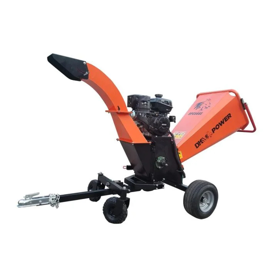
6IN KINETIC DRUM CHIPPER
OPC566E 6 INCH
CHIPPER ASSEMBLY GUIDE
MODEL: OPC566E
6 INCH KINETIC DRUM CHIPPER
WWW.DK2POWER.COM
DK2 USA EAST
6245 Industrial Parkway
Whitehouse, OH 43571
CONTACT US
KINETIC DRUM
DOT TOWABLE
KOHLER ENGINE
REV 1 – 9-19-2019
Advertisement

Related Manuals for Kohler DK2 POWER OPC566E

Summary of Contents for Kohler DK2 POWER OPC566E
- Page 1 Las Vegas, NV 89103 Burlington, Ontario, Canada L7L0A1 Whitehouse, OH 43571 1-702-331-5353 PARTS AND SERVICE 702-331-5353 OR WWW.DK2POWER.COM CONTACT US 6IN KINETIC DRUM CHIPPER KINETIC DRUM DOT TOWABLE KOHLER ENGINE OPC566E 6 INCH KINETIC DRUM CHIPPER REV 1 – 9-19-2019...
- Page 2 STEP 1: Open and unpack all items. Leave lots of working space. Inspect all parts. The CHIPPER is shipped in a crate. Remove all sides before you begin. NOTE: UPON INSPECTION OF PARTS IF YOU FIND ANY DAMAGE OR MISSING PARTS PLEASE CALL DK2 POWER AT 702-331-5353 OR CONTACT US VIA OUR WEBSITE WWW.DK2POWER.COM...
- Page 3 STEP 2: 1. PREPARE TO INSTALL THE AXLE 2. Slide chipper body to hang off side of the crate as shown. 3. Have a helper tip the unit forward while you complete the next step. Extend the unit off the crate REV 1 –...
-
Page 4: Bolts And Nuts
STEP 3: 1. Tip the unit forward 2. Install the axle using the 2 bolts and hardware provided and tighten. 2 BOLTS AND NUTS REV 1 – 9-19-2019... -
Page 5: Install The Wheels
STEP 4: 1. INSTALL THE WHEELS 2. Place the 2 black spacers on the axle first 3. Install the 2 wheel with nuts 4. Wheels should spin free. 5. Install end caps Spacers Washer then Nut and Pin End Cap REV 1 –... - Page 6 STEP 5: 1. INSTALL FEED CHUTE 2. With a helper slide the feed chute hinge pins into place, close and latch. REV 1 – 9-19-2019...
- Page 7 STEP 6 1. Holding the feed chute, lay the unit down as shown 2. Prepare to install the front hitch assembly. REV 1 – 9-19-2019...
- Page 8 STEP 7 1. Install the front hitch assembly 2. Use 8 bolts and hardware provide and secure tightly Use bolts provided both sides REV 1 – 9-19-2019...
- Page 9 STEP 8 1. Install the articulated front wheel assembly 2. Use bolt and pin hardware provide and semi tight to allow assembly to raise and lower. 3. Raise and pin when towing BOLT REV 1 – 9-19-2019...
- Page 10 STEP 9 1. Install the TOW BAR 2. Use 2 bolts and hardware provide and secure tightly 3. Tip unit forward and lower to level Use 2 bolts provided REV 1 – 9-19-2019...
- Page 11 STEP 10 1. Install the Lower Chip Chute 2. Carefully remove the mounting hardware from the frame so as to NOT drop into the cutting chamber. 3. You can OPEN the door while removing the hardware to be safe. Then reclose the door to mount the chute. 4.
- Page 12 STEP 11 1. INSTALL THE TOP CHIP CHUTE. 2. Use 3 HAND BOLTS and hardware provide and secure tightly 3. PLACE THE NYLON WASHER BETWEEN THE METAL WASHER AND THE CHUTE AS SHOWN. REV 1 – 9-19-2019...
- Page 13 STEP 12 1. Install the Safety shut-off bar 2. REMOVE THE PACKING NUT FROM THE BOLT AND DISCARD. IT WILL NOT BE NEEDED AND ONLY IS USED TO RETAIN THE MAIN HARDWARE DURING SHIPPING. 3. Install the 2 bolts and bar as shown. 4.
- Page 14 STEP 13 1. Install the Battery 2. Use 2 bolts and hardware provide and secure tightly 3. Connect the wiring as shown. 4. Be carefull as to not touch your wrench to metal frame when installing the positive red wire. Use 2 bolts provided REV 1 –...
- Page 15 REV 1 – 9-19-2019...
- Page 16 Ref.No. Description Ref.No.2 Description3 Rubber fixer strip Discharge(middle part) Kill switch cover Discharge(top part) Return lever spring Spacer Ø21*Ø25*95 Rubber plate Fore-wheel fixture Emergency stop bar Wheel 4.10-4 Bar fixture(left) Washer Ø16*Ø26*3 M10 lock nut Screw M16*12 Infeed hopper Dust cap Bar fixture(right) M24*1.5 slotted nut Seal cover(left)
-
Page 17: Maintenance
READ THE KOHLER ENGINE MANUAL SUPPLIED WITH YOUR UNIT FOR FULL ENGINE OPERATION, SAFETY, AND MAINTENANCE. YOUR UNIT HAS A COMMERCIAL KOHLER ENGINE WITH A 3YR PARTS AND SERVICE WARRANTY. FOR WARRANTY IN YOUR AREA CONTACT THE NEAREST KOHLER DEALER. - Page 18 OPERATION – BEFORE STARTING ENGINE CLEAR AREA OF ALL PEOPLE AND PROPERTY THAT COULD BE DAMAGED. THINK SAFETY. THIS CHIPPER CAN CAUSE INJURY IF SAFETY IS NOT ENFORCED. ONLY ONE OPERATOR SHOULD WORK THIS UNIT. NEVER HAVE ANOTHER PERSON IN THE AREA OR IN FRONT OF THE CHIP EXIT CHUTE. IF YOUR UNIT WILL NOT START –...
- Page 19 KOHLER ENGINES – KOHLER CH SERIES ENGINES COMMERCIAL 3 YR PARTS AND LABOR WARRANTY see your Kohler manual for specific warranty. DIESEL TRACTORS – Chassis component parts only, no labor, ENGINES – 1 YR KOHLER WARRANTY DK2 POWER OUTDOOR EQUIPMENT – 1-Year parts only, no labor.
Need help?
Do you have a question about the DK2 POWER OPC566E and is the answer not in the manual?
Questions and answers