
Summary of Contents for Cooper Tools Cleco mPro400GC
- Page 1 Quick Set-Up Guide PL12-1004EN 03/31/2010 mPro400 Global Controller For additional product information visit our website at http://www.cooperpowertools.com...
- Page 3 Disclaimer: Cooper Tools reserves the right to modify, supplement or improve this document or the product without prior notice. This document may not be reproduced in whole or in part in any way, shape or form, or copied to another natural or machine-readable language or to a data carrier, whether electronic, mechanical, optical or otherwise, without the express permission of Cooper Tools.
- Page 4 Cleco PL12-1004EN ® 03/31/2010 mPro400 Controller Page 4...
-
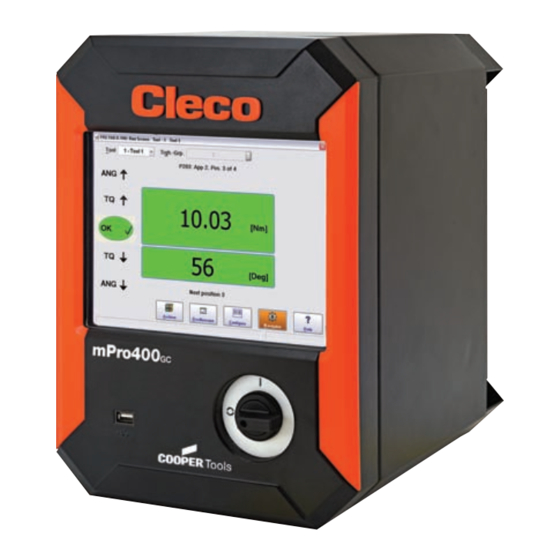
Page 5: Controller Description
Cleco PL12-1004EN ® mPro400 Controller 03/31/2010 Set-Up Guide: Controller description The mPro400 product line consists of three controllers; Master, Primary and Secondary. • Primary – Controls up to ten (10) Cordless Livewire tools and one (1) standard corded handheld or fixtured tool. This unit includes a servo. •... -
Page 6: Mounting The Controller
Cleco PL12-1004EN ® 03/31/2010 mPro400 Controller Mounting the Controller 1. Loosen the two long mounting screws at the bottom of the controller so the mounting plate can be separated from the controller, see Figure 1-17. 2. Figure 1-16 illustrates the bolt pattern for hanging the mounting plate on a wall. Note the hole-size dimensions so the correct size bolts are chosen. - Page 7 Cleco PL12-1004EN ® mPro400 Controller 03/31/2010 Tool Setup Figure 1-3: Navigator Screen 2. From the Navigator menu press TOOL SETUP. Tool Settings Primary Tool Figure 1-4: Tool Setup - Tool List 3. Touch the horizontal bar indicating the Primary tool to highlight it. Touch the Tool Settings button. Page 7...
- Page 8 Cleco PL12-1004EN ® 03/31/2010 mPro400 Controller Model Number Accept Button Serial Number Figure 1-5: Tool Setup - Tool Settings 4. Verify that the tool shown is the tool connected. Check the model and serial number. If the tool is correct press the ACCEPT button. In the window that appears press the ACCEPT button for that window.
-
Page 9: Accepting A Livewire Tool
Cleco PL12-1004EN ® mPro400 Controller 03/31/2010 Accepting a Livewire Tool Livewire communication requires three items; Tool, Controller, and Access point. Each item will require an IP address. All the IP addresses will be similar in structure such as 192.168.0.100, 192.168.0.110, 192.168.0.120, etc. The access point will also have a SSID name, which will need to be entered in the controller. - Page 10 Cleco PL12-1004EN ® 03/31/2010 mPro400 Controller RF (Radio Frequency) Settings IRDA Serial Port Selection Figure 1-7: Tool Setup - RF Settings 1. From the NAVIGATOR menu press the TOOL SETUP menu then RF Settings. Select IRDA Serial and the correct port depending on the port connected to at the base of the controller. See Figure 1-17.
- Page 11 Cleco PL12-1004EN ® mPro400 Controller 03/31/2010 Tool Install Select Tool Figure 1-9: Tool Setup - Tool List 1. Go to the Navigator menu and press TOOL SETUP. Press the screen at the tool number location you wish to install the tool. The row should highlight in orange. Position 1 is reserved for the Primary or corded tool.
-
Page 12: Programming A Basic Fastening Strategy
Cleco PL12-1004EN ® 03/31/2010 mPro400 Controller Model Number Accept Button Serial Number Figure 1-11: Tool Setup - Accepting the Tool 3. From the Navigator screen choose the TOOL SETUP menu. Press the Tool Settings button. Verify the tool model and serial number. If the information is correct press the Accept button at the bottom of the screen. -
Page 13: Auto Programming (Torque Control / Angle Monitor Only)
Cleco PL12-1004EN ® mPro400 Controller 03/31/2010 1.10 Auto Programming (Torque Control / Angle Monitor Only) Engineering Units Figure 1-13: Controller Settings 1. Before using the Auto Program feature go to ADVANCED menu from the Navigator screen, Controller Settings tab and choose the desired Engineering units. Press the Navigator button to save settings. -
Page 14: Manual Programming
Cleco PL12-1004EN ® 03/31/2010 mPro400 Controller 1.11 Manual Programming Figure 1-15: Manual Programming 1. Touch the Torque High Limit field and a keyboard will appear. Enter the desired High Torque value. Whole numbers do not require decimal points. They will be added automatically. Use the down arrow on the keyboard to move the keyboard down so the next field can be entered. - Page 15 Cleco PL12-1004EN ® mPro400 Controller 03/31/2010 Figure 1-16: Mounting Information 10.38” (263mm) 4x 1.315” 4x 7.750” (33.4mm) (197mm) 1.825” (46.4mm) 2x 1.250” (31.8mm) 2x 12.500” (318mm) 14.88” (378mm) 0.075” (1.9mm) 10x .270” (6.86mm) 10x .503” (12.8mm) 10x .313” (1.95mm) Page 15...
- Page 16 Cleco PL12-1004EN ® 03/31/2010 mPro400 Controller Figure 1-17: Connector Locations Mounting Bracket Mounting Bracket Screw Screw Legend X1 = Ethernet Connector #1 X7 = Anybus Fieldbus X2 = Ethernet Connector #2 X8 = Anybus Fieldbus X3 = USB ports (2) X9 = Tool Connector X4 = Serial Connector #1 X10 = System Bus Connector...
- Page 17 Cleco PL12-1004EN ® mPro400 Controller 03/31/2010 1.12 Inputs and Outputs - Primary Controller Note: Pins are numbered exactly as they are on the controller, Pins 1 and 13 at the bottom, Pins 12 and 24 at the top. Pin # Signal Description Pin # Signal Description...
- Page 18 Cleco PL12-1004EN ® 03/31/2010 mPro400 Controller 1.12.1 Inputs and Outputs - Secondary Controller Note: Pins are numbered exactly as they are on the controller, Pins 1 and 13 at the bottom, Pins 12 and 24 at the top. Note: Some Inputs and Outputs are fixed, not programmable. Pin # Signal Description Pin #...
- Page 19 Cleco PL12-1004EN ® mPro400 Controller 03/31/2010 1.12.2 Connections Utilizing the Internal 24-volt Supply (Primary, Secondary, Master) INPUTS: Pins 11 and 23 (Common GND) are the Input “returns”. Controller Internal 24-volt Supply Pins 11 and 23 must be jumpered to Pins 12 and 24 respectively. OUTPUTS: Pins 2 and 14 (Output Common) are the voltage source for the Outputs.
-
Page 20: Sales & Service Centers
+44-2476-3089 69 Houston, TX 77041 Tel: 425-497-0476 Tel: 713-849-2364 Fax: 425-497-0496 Fax: 713-849-2047 Cooper Tools Cooper Tools Cooper Tools Industrial Cooper Power Tools P.O. Box 1410 5925 McLaughlin Road Ltda. GmbH & Co. OHG Lexington, SC 29071-1410 Mississauga, Ontario Av. Liberdade, 4055...
Need help?
Do you have a question about the Cleco mPro400GC and is the answer not in the manual?
Questions and answers