Table of Contents
Advertisement
Quick Links
La Marche Manufacturing Company |www.lamarchemfg.com
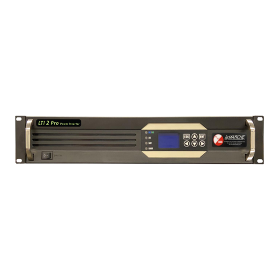
LTI2 PRO
Power Inverter
Installation and Operation Manual
This manual is subject to change without notice. You may obtain the newest version of the manual at
www.lamarchemfg.com
106 Bradrock Dr. Des Plaines, IL 60018-1967
CPN 143460
Instruction Drawing Number: P25-LLTI2PRO-1
Tel: 847 299 1188
Fax: 847 299 3061
Revision A00
Rev. Date: 09/20
ECN:22666
Advertisement
Table of Contents

Subscribe to Our Youtube Channel
Related Manuals for La Marche LTI2 PRO


Summary of Contents for La Marche LTI2 PRO
- Page 1 La Marche Manufacturing Company |www.lamarchemfg.com LTI2 PRO Power Inverter Installation and Operation Manual This manual is subject to change without notice. You may obtain the newest version of the manual at www.lamarchemfg.com 106 Bradrock Dr. Des Plaines, IL 60018-1967 CPN 143460...
-
Page 2: Important Safety Instructions
Important Safety Instructions Before using this equipment, read all manuals and other documents related to this inverter and other equipment connected to this unit. Always have a copy of an inverter’s manual on file nearby, in a safe place; if a replacement copy of a manual is needed, it can be found at www.lamarchemfg.com. -
Page 3: Unit Location
If any damage is observed, take pictures and contact the carrier immediately to file a damage claim. Contact La Marche for a Return Material Authorization number to have the inverter sent back for evaluation and repair. -
Page 4: Table Of Contents
Model Scope/General Description ........................ 1 Understanding the Model Number ....................... 1 Optional Accessories Included in the Inverter ....................1 Equipment Handling ........................2 Storing the LTI2 PRO ........................2 Moving the LTI2 PRO ........................2 Installation ............................. 2 Mounting the LTI2 PRO ........................ 2 2.1.1... -
Page 5: Table Of Figures
Table 3 - LED and Alarm Indications Details ....................7 Table 4 - Troubleshooting Guide ......................... 9 Table 5 - Wire Size/Area Table ........................13 Figure 1 - LTI2 Pro Overview ........................1 Figure 2 - Rack Mounting Brackets ......................3 Figure 3 - Rack Mounting ........................... 3 Figure 4 - Input and Output Connections ..................... -
Page 6: Model Scope/General Description
(if any) refer to the cover page of the manual package. If the manual package that is included with the inverter is no longer available, contact La Marche and provide the model or serial number to receive a... -
Page 7: Equipment Handling
Storing the LTI2 PRO If the LTI2 PRO is to be stored for more than a few days after delivery, it should be stored within its shipping container. The location chosen for storage should be within an ambient temperature of -40 to 158° F (-40 to 70°C) with a non-condensing relative humidity of 0 to 95%. -
Page 8: Rack-Mounting The Lti2 Pro
The LTI2 PRO enclosure can be rack mounted on a standard 19/23” relay rack. For rack-mounting install the brackets to the front of the LTI2 PRO enclosure, seen in Figure 2. Flush mount the LTI2 PRO enclosure to the relay rack. -
Page 9: Input Wiring
2.2.1 Input Wiring WARNING: Connecting the battery to the Inverter may cause a spark at the point of connection. There is a RISK OF EXPLOSION in hazardous areas or locations where explosive gases have accumulated. Access the rear of the inverter and locate the DC Input connection terminal. Connect DC wiring to the inverter per figure-3. -
Page 10: Alarm Connections
2.2.3 Alarm Connections The LTI2 PRO inverter is equipped with a single set of Form ‘C’ dry-type relay contacts (60 VDC @ 0.5A rating) for Alarm. Figure 5 - Alarm Connections Operation Operation Mode 3.1.1 AC Power Supply Mode AC inverter working mode: Inverter employs mains for load when there are mains and switches to the inverter when the mains is abnormal. -
Page 11: Start-Up Sequence
Start-Up Sequence 3.2.1 Commissioning Check whether the DC input voltage is consistent with the nameplate label; in case of any inconsistency, please do not apply the DC power supply to an inverter, in order not to cause any damage! Check whether the wiring polarity of the DC input is correct;... -
Page 12: Led And Alarm Indications Details
3.3.2 LED and Alarm Indications Details Mode LED Status Indicator Light Buzzer AC Mode Solid Green DC Mode Solid Blue Mains LED Status Indicator Light Buzzer Normal AC Voltage Solid Green High AC Voltage Quick Flashing Red One Sound Every 3s Low AC Voltage Slow Flashing Red One Sound Every 3s... -
Page 13: Lcd Menu
3.3.3 LCD Menu Figure 8 – LED and Alarm Indications Details Figure 9 - LED and Alarm Indications Details... -
Page 14: Troubleshooting
Low- voltage, Cut off the load to test whether the high- Operating fault inverter normally operates and the Consult with La Marche mfg. voltage, voltage of each point is normal. overload protection. Too high or Use a Multimeter to measure the... -
Page 15: Appendix A: Technical Specifications
Appendix A: Technical Specifications The La Marche LTI2 PRO Inverter is designed for 1kVA to 6kVA with pure sine wave 120VAC 60Hz power at output from a 48V or 125V DC input source. This inverter is equipped with standard features such as voltage regulation, under/over–voltage conditions, and overload protection with >=85% efficiency. -
Page 16: Technical Specifications (Cont
Technical Specifications (Cont…) Voltage Accuracy (V) 120±1.5% Frequency Accuracy (Hz) 60±0.1% Waveform Pure sine wave Total harmonic distortion ≤3% (linear load) (THD) Dynamic response time 5% (load 0←→100%) AC Output Power factor (PF) Overload capacity 110%-130% 60s 131%-150% 10s Inversion efficiency ≥85% (80% resistive load) Inverter - Bypass (ms) -
Page 17: Technical Specifications (Cont
Technical Specifications (Cont…) PROTECTION The output current will gradually increase after the inverter is turned on, Current Walk-In eliminating surges and overshoot Current Limit Overload protection Temperature Over Temperature Shutdown Protection ENVIRONMENTAL Operating 32 to 122˚F (0 to 50˚C) Temperature Relative Humidity 0 to 95% (non-condensing) Cooling... -
Page 18: Appendix B: Power Cabling Guide
Appendix B: Power Cabling Guide Use the following formulas and table to determine proper wire size for minimal voltage drop. At distances exceeding 10 feet, the DC wire size should be chosen to keep the voltage difference between the inverter’s DC input terminals and the battery at less than 1/2 volt when the inverter is fully loaded. -
Page 19: Appendix C: Manufacturer's Warranty
Should minor adjustments be required, the local La Marche Sales Representative should be contacted to provide this service. All sales are final. Only standard La Marche units will be considered for return. A 25% restocking fee is charged when return is a factory authorized. Special units are not returnable. -
Page 20: Appendix D: Document Control And Revision History
Appendix D: Document Control and Revision History Part Number: 143460 Instruction Number: P25-LLTI2PRO-1 Issue ECN: 22666 - 09/20 22666 - 09/20...
Need help?
Do you have a question about the LTI2 PRO and is the answer not in the manual?
Questions and answers