Advertisement
Quick Links
Note: For EMC the ambient temperature limit for the
Opus plus range is 24 deg C (or 25 deg if the speed pot
is restricted to ¼ turn above minimum).
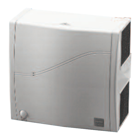
1.0 Typical arrangements
Figure 1. Wall mounting
Figure 2. Ceiling mounting
2.0 Introduction
A surface mounted unit designed to serve toilets, store rooms,
small offices, restaurants, smoking areas etc. for installation
on the ceiling or wall of the area served.
For full specification, dimensions and weights etc. refer to
catalogue.
The range includes single and twin fan models, air inlet is via
front side mounted filters exiting via a 125mm spigot at the
rear. Back-draught shutters are an optional extra LED indicators
on the case cover provide local run/fail status indication.
Opus fan range
Code
Description
OPUS 100-B
A single fan unit
OPUS 100-BP
A single fan unit with
integral PIR
OPUS 100-2B
A twinfan unit with
run and standby and
auto duty share
OPUS 100-2BP
A twinfan unit with
run and standby and
auto duty share and
integral PIR
OPUS 150-B
A dual fan unit with
both motors running
OPUS 150-BP
A dual fan unit with
both motors running
and integral PIR
Nuaire: A Trading Division of Polypipe Limited Western Industrial Estate Caerphilly United Kingdom CF83 1NA
T: 029 2088 5911 F: 029 2088 7033 E: info@nuaire.co.uk W: www.nuaire.co.uk
Opus 100-B & 150-B
Surface Mounted Extract Fans
Installation and Maintenance
3.0 Installation
The installation must be completed by competent persons in
accordance with good industry practice and should conform
to all governing and statutory bodies i.e. IEE, CIBSE, COHSE,
HVCA etc.
The unit comprises a full-length removable access cover to
reveal and remove fan internals and facilitate first fix
installation. Ensure that all electrical and ducting services are
compatible to the installation and the desired control function
before proceeding.
Figure 3. Removing the impeller transit-packing pieces (1 and 2).
Power/FLC
at full speed
4.0 Mechanical installation
100W/0.39A
Remove the unit internals; release the two M4 cover screws
100W/0.39A
and remove the cover, lift the electronic control module (about
100W/0.39A
15mm) to disengage from the base socket. Disconnect the PIR
(if fitted) and unscrew the four M5 x 35mm blower assembly
retaining screws and lift out the fan unit internals.
100W/0.39A
Select a solid non-reverberant mounting position with a mini-
mum of 50mm from any side-wall and ceiling. Observe the
footprint detail, particularly the mains cable entry point, mark
200W/0.78A
and drill the chosen structure and fix the case with appropriate
200W/0.78A
anchor bolts or screws. Connect and fix.
1
WARNING -
REMOVE TRANSIT PACKING PIECES BEFORE
APPLYING POWER TO UNIT
Motor plate
Electrical
fixing screws (2)
terminal block
1
Ca
The EMC Directive
2014/30/EU
The Low Voltage
Directive
2014/35/EU
Earth post
Cable grommet
2
Motor assembly
12. 05. 17. Leaflet Number 670967
Advertisement

Related Manuals for NuAire Opus 100-B


Summary of Contents for NuAire Opus 100-B
- Page 1 Connect and fix. both motors running and integral PIR Nuaire: A Trading Division of Polypipe Limited Western Industrial Estate Caerphilly United Kingdom CF83 1NA T: 029 2088 5911 F: 029 2088 7033 E: info@nuaire.co.uk W: www.nuaire.co.uk 12. 05. 17. Leaflet Number 670967...
- Page 2 Installation and Maintenance Opus 100-B & 150-B Surface Mounted Extract Fans 5.0 Electrical installation Figure 6. Removing the impeller transit-packing pieces (1 and 2). Notes Motor plate Electrical To ease electrical connection, remove the six-way Earth post Cable grommet fixing screws (2)
- Page 3 Installation and Maintenance Opus 100-B & 150-B Surface Mounted Extract Fans 7.0 Dimensions (mm) and Weights Dimensions (mm) and weights Fan Unit Weight OPUS100-B 5 kg OPUS100-BP 5 kg OPUS100-2B 6 kg OPUS100-2BP 6 kg OPUS150-B 6 kg OPUS150-BP 6 kg...
- Page 4 Installation and Maintenance Opus 100-B & 150-B Surface Mounted Extract Fans 8.0 Maintenance 10.0 Replacement of parts Nuaire keep extensive stocks of spares for quick delivery, when ordering please clearly identify the part required and Isolation - Before commencing work...
Need help?
Do you have a question about the Opus 100-B and is the answer not in the manual?
Questions and answers