Table of Contents
Advertisement
Quick Links
OPERATOR'S MANUAL
DIGITALLY CONTROLLED POWER MODULE SYSTEM
1/9 RACK SIZE 200 WATT POWER MODULES
FOR USE WITH KEPCO POWER MODULE CONTROLLERS
KEPCO INC.
An ISO 9001 Company.
IMPORTANT NOTES:
1)
This manual is valid for the following Model and associated serial numbers:
MODEL
2)
A Change Page may be included at the end of the manual. All applicable changes and
revision number changes are documented with reference to the equipment serial num-
bers. Before using this Instruction Manual, check your equipment serial number to identify
your model. If in doubt, contact your nearest Kepco Representative, or the Kepco Docu-
mentation Office in New York, (718) 461-7000, requesting the correct revision for your par-
ticular model and serial number.
3)
The contents of this manual are protected by copyright. Reproduction of any part can be
made only with the specific written permission of Kepco, Inc.
Data subject to change without notice.
©2020, KEPCO, INC
P/N 228-1924-r1
KEPCO, INC.
131-38 SANFORD AVENUE
MST-MHT SERIES
POWER MODULE
MODELS
MST 6-20MHT, MST 15-12MHT,
MST 25-8MHT, MST 36-5MHT,
MST 55-3.5MHT, MST 75-2.5MHT,
MST 100-2MHT, MST 150-1.2MHT
SERIAL NO.
FLUSHING, NY. 11355 U.S.A.
email: hq@kepcopower.com
REV. NO.
KEPCO
THE POWER SUPPLIER™
TEL (718) 461-7000
World Wide Web: www.kepcopower.com
®
FAX (718) 767-1102
Advertisement
Table of Contents

Subscribe to Our Youtube Channel
Summary of Contents for KEPCO MST-MHT Series
- Page 1 Before using this Instruction Manual, check your equipment serial number to identify your model. If in doubt, contact your nearest Kepco Representative, or the Kepco Docu- mentation Office in New York, (718) 461-7000, requesting the correct revision for your par- ticular model and serial number.
- Page 3 (EN61010-1:2001 Cl. 6, Cl. 7, Cl.8, and Cl. 9) 2. This power supply is designed for stationary installation, with mains power applied via a KEPCO Rack Adapter.
- Page 4 Pollution Degree 2. Hazardous voltages are present within this product during normal operation. This product is designed for use in a KEPCO Rack Adapter product. Operation of this product without a rack adapter should never be attempted. The product should never be operated with the cover removed unless equivalent protection of the operator from accidental contact with hazardous internal voltages is provided.
-
Page 5: Table Of Contents
Fault Protection ............................3-5 3.7.1 Fault Recovery........................... 3-6 3.7.2 Fixed Overvoltage Detector ....................... 3-6 3.7.3 Overcurrent Tracking Detector ......................3-6 3.7.4 Overtemperature Detectors ....................... 3-6 3.7.5 A-C Loss Detector ..........................3-7 3.7.6 Open Sense/Power Wire Protection ....................3-7 MST-MHT SERIES 071320... - Page 6 Current Sense Zero Adjust (R50) ..................... 3-10 3.9.5 Output Current I Zero Adjust (R51) ....................3-11 3.9.6 Voltage Reference Adjust (R47) ....................... 3-11 3.9.7 Current Reference Adjust (R48) ....................... 3-11 3.9.8 Current (I ) Full Scale Adjust (R52) ....................3-12 MST-MHT SERIES 071320...
- Page 7 Functions of Internal Controls .......................2-1 Front Panel Controls and Indicators .....................2-2 Rear Terminations ..........................2-3 Secondary Address Selection .......................2-4 DC Output Connector/Adapter Kit Terminal Designations ..............2-11 Error Messages .............................3-1 Maximum External Capacitance Values to Ensure Dry Switching ............3-4 MST-MHT SERIES 071320...
-
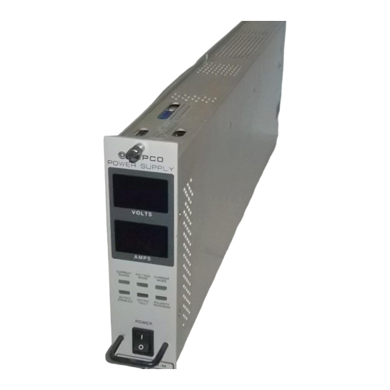
Page 8: Mst Power Supply
FIGURE 1-1. MST POWER SUPPLY MST SERIES 071320... -
Page 9: Section 1 - Introduction
7" x 1-3/4” cross-section allows nine independently controlled modules to be mounted abreast in a standard (19" x 7" x 20.9") Kepco Model RA 55H rack adapter or 5 modules in a standard (9.6” x 7” x 20.9”) Kepco Model CA 400H case. -
Page 10: Specifications
0-100 122.4 MST 150-1.2MHT 0-150 183.6 NOTE: Minimum 2% above Programmable (max.), SPECIFICATIONS The MST-MHT Series electrical and mechanical specifications are listed in Tables 1-1 and 1-2. TABLE 1-2. MST-MHT GENERAL SPECIFICATIONS SPECIFICATIONS RATING/DESCRIPTION CONDITION INPUT nominal 100-250V a-c Single phase A-C Voltage ... - Page 11 Tracks output current. Shutdown selectable upon either See Par. 3.7.3 exceeding rated current by 10% or immediate Overtemperature Thermostat See PAR. 3.7.4 Open sense wire Automatic detection with power shutdown See PAR. 3.7.6 Backup current limit Tracks output current at 110% MST-MHT SERIES 071320...
-
Page 12: Features
Control of the MST-MHT Power Module is via the IEEE 1118 2-wire serial bus operating at 375KHz; as many as 27 separate modules of the MST-MHT Series can be addressed via the bus. Decoders for RS232, IEEE-488 and VXI are available in modular form and stand-alone types. -
Page 13: Mst-Mht Power Supply, Mechanical Outline Drawing
FIGURE 1-1. MST-MHT POWER SUPPLY, MECHANICAL OUTLINE DRAWING MST-MHT SERIES 071320... -
Page 14: Status Indicators
(see PAR. 3.7.4). • AC loss: Activated if loss of source power detected (see PAR. 3.7.5). • Open power lead and sense wire: Activated if an open sense wire or open power lead is detected (see PAR. 3.7.6). MST-MHT SERIES 071320... -
Page 15: Series Configurations
0 to 2V signal corresponds to 0 to I ACCESSORIES The MST-MHT Power Module is designed for installation in Kepco Rack Adapter Model RA 55H which accommodates nine 1/9 rack size power modules. With a 1/9 rack Controller module installed, the RA 55H will accommodate eight 1/9 rack power modules. -
Page 17: Section 2 - Installation
PANEL OPENINGS AND THE TOP OF THE CASE MUST BE KEPT CLEAR FROM OBSTRUCTIONS TO INSURE PROPER AIR CIRCULATION. Maximum ambient temperature for installed MST-MHT modules is 45°C. See technical manuals for RA 55H or CA 400H rack MST-MHT SERIES 071320... -
Page 18: Front And Rear Views Of The Mst-Mht Power Module
Goes on to indicate that unit is operating as “slave” module when used in a parallel configuration (see PAR. 3.5). VOLTS meter Displays output voltage. AMPS meter Displays output current. FIGURE 2-1. FRONT AND REAR VIEWS OF THE MST-MHT POWER MODULE MST-MHT SERIES 071320... -
Page 19: Installation/Removal
MST-MHT modules on the bus using the secondary address. The secondary address from 0 to 30 is selected by DIP selector switch S1 accessed through the top of the unit (see Figure 2-2) and can be changed in accordance with Table 2-4. This address is set at Kepco to 1. - Page 20 If the Power Module is already installed in a Rack Adapter and it is necessary to change the secondary bus address, the Power Module must first be removed from the Rack Adapter as described in PAR.2.5.3 below. MST-MHT SERIES 071320...
-
Page 21: Installation
2. To ensure full engagement of the module interconnect to the RA 55H Rack Adapter or CA 400H case, pull out the two slotted captive thumb screws (at the front of the Module) and turn counterclockwise until the threads engage. MST-MHT SERIES 071320... -
Page 22: Removal
RA 55H safety ground terminal via the GROUND pins of the AC/Control Bus connector (Fig- ure 2-6). For operation of the MST-MHT Power Module outside the RA 55H Rack Adapter, con- sult Kepco Applications Engineering for assistance. WARNING RA 55H RACK ADAPTER MUST ALWAYS BE GROUNDED WHEN CONNECTED TO AN A-C POWER SOURCE. -
Page 23: Preliminary Check-Out
2.7.1 REQUIRED EQUIPMENT • Host computer w/communication cable for selected controller • Kepco Controller (See PAR. 1.4.1). • RA 55H or CA 400H rack adapter; alternative is to use Input Power/Communication Cable (see Table 1-3) • Load Interface Cable or mating load connector (see Table 1-3) •... -
Page 24: Initial Checkout Setup
Clear command via the Host Computer prior to issuing other commands. For proper time delays between commands refer to PAR. 3.1.2. For details on the SCPI com- mands, refer to the Instruction Manual for the applicable controller (see PAR. 1.4.1). MST-MHT SERIES 071320... -
Page 25: Checkout Procedure
4) verify that DVM reads +E (e.g. for MST 36-5MHT DVM reads 36V d-c). 5. Issue command from the host computer to read back voltage. MEAS:VOLT? Verify that readback voltage is +E (e.g. 36V for MST 36-5MHT). MST-MHT SERIES 071320... -
Page 26: Power Module To Load Interface
(voltage mode) or infinite output impedance (current mode): All volt- age sources have some amount of impedance which increases with frequency and all current sources have impedance which decreases with frequency (see Figure 2-5). 2-10 MST-MHT SERIES 071320... -
Page 27: Connection, General
Adapter Kit 219-0618 is must be installed on the DC Output Connector at the rear of the chassis to meet the all specifications listed in Table 1-1. For the DC Output Connector pin designations on MST-MHT units via Adapter Kit 219-0618 refer to Table 2-5 and Figure 2-6. 2-11 MST-MHT SERIES 071320... -
Page 28: Load Connection With Local Error Sensing
(pins 6 to 5 and 3 to 2, respectively). NOTE: As electrolytic capacitors are normally polarized make sure that the positive (+) terminal of each one are respectively connected to the +V (pin 6) and -S (pin 2) pins. 2-12 MST-MHT SERIES 071320... -
Page 29: Connector Locations And Pin Assignments
NOTE: To remove Adapter Kit 219-0618, refer to Kit 219-0618 RA 55 Connector Adapter Kit Instruction Sheet (see PAR. 1.1 for download instructions). FIGURE 2-6. CONNECTOR LOCATIONS AND PIN ASSIGNMENTS 2-13/(2-14 Blank) MST-MHT SERIES 071320... -
Page 31: Section 3 - Operation
• After an OUTP ON or OFF, wait approximately 300 milliseconds. • After a Confidence Test command or an Internal Self Test, wait approximately 400 milli- seconds. • After a Reset command, wait approximately 300 milliseconds. MST-MHT SERIES 071320... -
Page 32: Operating Modes
Voltage and Current operating modes. Polarity reversal can be programmed in advance of output activation (Standby) or “on-the-fly” (Active) while the out- put is enabled; both methods employ a “dry-switching” scheme in order to extend relay life. MST-MHT SERIES 071320... - Page 33 T = Time (Sec) = 2 seconds CAUTION: FAILURE TO OBSERVE THE “DRY SWITCHING” CRITERIA NOTED ABOVE WILL CAUSE DAMAGE TO THE RELAYS AND VOID THE KEPCO WARRANTY. In order to allow for settling time, the user should wait approximately 300 milliseconds after com- pletion of polarity reversal before sending a status query in order to avoid erroneous fault mes- sages.
-
Page 34: Output Enable And Disable
This method determines “N”, the minimum number of power modules needed to support the load. For redundant applications this number is increased based on the desired redundancy factor (N+1, N+2, etc.). For non- MST-MHT SERIES 071320... -
Page 35: Series Operation
Power Modules which, because of the sequential turn-on characteristic, may be exposed to greater risk during output enabling and disabling sequences. Users wishing to operate MST- MHT Power Modules in series are directed to contact Kepco Applications Engineering for spe- cific guidance. -
Page 36: Fault Recovery
PAR. 3.7a. The thermostat will reset upon return of the heat sink to acceptable operating temperature, however the module recovery procedure (see PAR. 3.7.1) must still be performed. MST-MHT SERIES 071320... -
Page 37: A-C Loss Detector
0.5V maximum specified headroom resulting in the same situation as described above. . If the error sense lead connections appear to be correct, the user should double-check the size of the power leads to verify adequate margin. Contact Kepco Applications Engineering for assistance if necessary. -
Page 38: Calibration
4W, a 100W shunt is adequate for all models) • Miscellaneous programming interface cables, load cables, etc. Install the MST-MHT Series power module under test (UUT) in the calibration test set-up shown in Figure 3-1 MST-MHT SERIES 071320... -
Page 39: Calibration Test Set-Up
O2- S2- CS FIGURE 3-1. CALIBRATION TEST SET-UP MST-MHT SERIES 071320... -
Page 40: Volts Reference Adjust (R49)
3. Connect voltmeter to test connector J5, pins 4 (CSNS - Current Sense) and 6 (GND) and verify meter reads 0.00000V ± 500V. If meter reading is outside these limits, adjust potenti- ometer R50 for 0.00000V ± 50V. 3-10 MST-MHT SERIES 071320... -
Page 41: Output Current I Ozero Adjust (R51)
6. Verify that the read back value (step 5) is within ± 1 LSB (4096) of the programmed value (step 3). If readback value exceeds acceptable range, adjust R48 for readback value within ±0.5 LSB (1/8192) of the programmed value. 3-11 MST-MHT SERIES 071320... -
Page 42: Current (I O ) Full Scale Adjust (R52)
± 1 LSB (1/4096) of . If the acceptable range is exceeded, adjust R52 until measured current is within ±0.5 LSB (1/8192) of read back current, repeating steps 1 through 5 as necessary. 3-12 MST-MHT SERIES 071320...
Need help?
Do you have a question about the MST-MHT Series and is the answer not in the manual?
Questions and answers