
Related Manuals for BEKA BA574C

Summary of Contents for BEKA BA574C
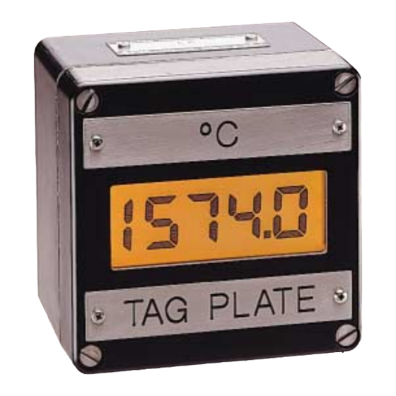
- Page 1 BA574C field mounting indicating temperature transmitter issue 4 Issue: 4 26th September 2008...
-
Page 2: Table Of Contents
5.8 Calibrating the internal references 5.8.1 Conditioning internal references 11. Backlight 5.8.2 Voltage input reference 5.8.3 3-wire RTD reference 5.8.4 4-wire RTD reference 5.8.5 Output current reference The BA574C is CE marked to show compliance with the European EMC Directive 2004/108/EC... - Page 3 You should only enter this section of the programme if you are sure that you want to carry out this calibration. By following the notes in this manual you should be able to set up your BA574C without any problem. If you do run into difficulties however Section 8 (Maintenance) provides some guidance on typical problems you may find during commissioning.
-
Page 5: Description
4/20mA output proportional to seconds. temperature, plus a display in C or Voltage inputs may be scaled allowing the BA574C to ..For 1 second display variables other than temperature. Optional alarms provide two galvanically isolated For less than 0.5... -
Page 6: Electrical System Design
3. ELECTRICAL SYSTEM DESIGN 4. INSTALLATION A BA574C indicating transmitter will operate from any dc voltage between 10 and 30V. When 4.1 Location designing a loop it is therefore necessary to ensure The BA574C indicating transmitter can be supplied that the voltage between terminals 5 & 6 in either a glass reinforced polyester (GRP), or an between 10 and 30V at all output currents. -
Page 7: Installation Procedure
4.2 Installation Procedure 4.3 EMC illustrates instrument installation The BA574C complies with the requirements of the procedure. European EMC Directive 2004/108/EEC. specified immunity all wiring should be in screened a. Remove the enclosure cover by unscrewing twisted pairs. the four captive 'A' screws. -
Page 8: Summary Of Programme Menu Functions
Sets display to C or information is stored in permanent memory. See section 5.3.2 All new BA574C indicators are supplied calibrated 'rESn' Display resolution as requested at the time of ordering. If calibration Selects low or high display resolution. -
Page 9: For Voltage Inputs
Summary of Programme Menu functions 'Cond' Conditioning of internal references WARNING! Display Functions This sub-menu is password protected. It is not necessary to For Voltage Inputs carry out this operation before putting instrument into ''d.P.' Decimal point service. Positions the dummy decimal point between any of the display digits or This sub-menu enables the internal turns it off. - Page 12 5.2 Transmitter input 'InPut' Display Resolution This function conditions the transmitter to accept a Type Low (Lo) High (Hi) thermocouple 'tHC', resistance thermometer 'rtd' or a voltage 'UOLt' input. To define the transmitter input select 'InPut' from the Programme Menu and press P which will reveal the current setting.
-
Page 13: Position Of Display Decimal Point
5.4 For resistance thermometer inputs After selecting voltage input from the 'InPut' menu, press P to reveal the 'd.P.' sub-menu. Press P 5.4.1 Types of resistance thermometer 'tYPE' again to display the current decimal point position. The decimal point can be moved or turned off by The transmitter may be conditioned to accept pressing the Up or Down push-button, followed by 3-wire, 4-wire or differential Pt100 resistance... -
Page 14: 4/20Ma Output Current Calibration
'InPut' Note: If a complete loop including a primary and ''dISP'. element, BA574C temperature transmitter and a load are being calibrated, the Trim Menu is the Select the input voltage 'InPut' and press P which preferred method. -
Page 15: Calibrating The Internal References
5.8.2 Voltage input reference 'U.IP' test equipment and have read the With the BA574C input terminals connected to an following instructions. routine accurate voltage calibrator, select 'U.IP' from the calibration of the the instrument use the 'Cond' sub-menu and press P. -
Page 16: Output Current Reference
Alternatively, the Select '4rtd' from the 'Cond' sub-menu and press P. temperature at the BA574C input terminals may be The transmitter will display scrolling decimal points measured and the voltage calibrator corrected for... -
Page 17: Periodic Re-Calibration Using Trim Menu
DVM or other instrument. When correct, press the E button If the BA574C internal references are used to make frequent calibration changes, we recommend that to store the trim correction in permanent memory... - Page 18 F. Select C and press E to The following steps explain how, using the Trim return to the sub-menu. Menu, the BA574C transmitter may be calibrated against an external reference, such as a voltage Step 6 Resolution source or temperature calibrator. Alternatively, the...
-
Page 19: Maintenance
8.1 Fault finding during commissioning display the thermocouple temperature. If the BA574C transmitter fails to function during Adjust the display with the Up and commissioning the following procedure should be Down buttons until it is -10.0... -
Page 20: Fault Finding After Commissioning
8.2 Fault finding after commissioning ENSURE PLANT SAFETY BEFORE STARTING MAINTENANCE If a BA574C fails after it has been functioning correctly the procedure shown in section 8.1 should be followed. 8.3 Servicing The BA574C uses surface mount components and cannot be serviced on-site. Electronic assemblies... -
Page 21: Accessories
10.0 ALARMS The BA574C can be supplied with two solid state single pole alarm outputs. Each output may be programmed as a high or low alarm with a normally open or a normally closed output. - Page 22 The alarms relate to the digital display and the 'AcSP' Access setpoint setpoints are shown in the same units as the Sub-menu which enables the function display. allowing direct access to the alarm setpoints from the operating mode, and The following table summaries each of the alarm defines a separate security code.
- Page 23 Fig 11 Programme structure for optional alarms...
-
Page 24: Description Of Programmable Functions
10.3 Description of programmable functions To check or change the alarm output status select 'no.nc' from the alarm sub-menu and press P reveal The following sections contain detailed descriptions of each programmable function. They should be the current setting. The function can be changed read in conjunction with the programme structure by pressing the Up or Down button followed by the shown in Fig 11. -
Page 25: Access Setpoint
Up and Down push-buttons, and the P button to display mode. move to the next digit. When the required setpoint Access to the alarm setpoint when the BA574C has been entered, pressing will return the transmitter is in the display mode is obtained by... -
Page 26: Backlight
18 and 30V dc as shown in Fig 13. If the BA574C is only used for indication, i.e. the 4/20mA output current is not used, the backlight may be powered from the instrument power supply by linking terminals 5 &...
Need help?
Do you have a question about the BA574C and is the answer not in the manual?
Questions and answers