Table of Contents
Advertisement
Quick Links
Installation, Operation,
and Maintenance
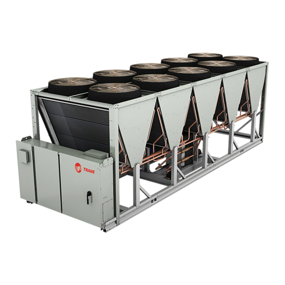
Ascend™ ™ Air-Cooled Chiller — Model ACS
140 to 230 Nominal Tons
Only qualified personnel should install and service the equipment. The installation, starting up, and servicing of heating, ventilating, and
air-conditioning equipment can be hazardous and requires specific knowledge and training. Improperly installed, adjusted or altered
equipment by an unqualified person could result in death or serious injury. When working on the equipment, observe all precautions in the
literature and on the tags, stickers, and labels that are attached to the equipment.
October 2019
S S A A F F E E T T Y Y W W A A R R N N I I N N G G
A A C C - - S S V V X X 0 0 0 0 2 2 C C - - E E N N
Advertisement
Table of Contents

Related Manuals for Ingersoll-Rand Trane Ascend ACS

Summary of Contents for Ingersoll-Rand Trane Ascend ACS
- Page 1 Installation, Operation, and Maintenance Ascend™ ™ Air-Cooled Chiller — Model ACS 140 to 230 Nominal Tons S S A A F F E E T T Y Y W W A A R R N N I I N N G G Only qualified personnel should install and service the equipment.
- Page 2 Introduction Read this manual thoroughly before operating or W W A A R R N N I I N N G G servicing this unit. P P r r o o p p e e r r F F i i e e l l d d W W i i r r i i n n g g a a n n d d G G r r o o u u n n d d i i n n g g R R e e q q u u i i r r e e d d ! ! Warnings, Cautions, and Notices F F a a i i l l u u r r e e t t o o f f o o l l l l o o w w c c o o d d e e c c o o u u l l d d r r e e s s u u l l t t i i n n d d e e a a t t h h o o r r...
- Page 3 I I n n t t r r o o d d u u c c t t i i o o n n W W A A R R N N I I N N G G A A l l l l U U n n i i t t I I n n s s t t a a l l l l a a t t i i o o n n s s Startup MUST be performed by Trane, or an authorized F F o o l l l l o o w w E E H H S S P P o o l l i i c c i i e e s s ! ! agent of Trane, to VALIDATE this WARRANTY.
-
Page 4: Table Of Contents
Table of Contents Model Number Information ....6 Evaporator Piping ..... . . 22 Evaporator Piping Components . - Page 5 T T a a b b l l e e o o f f C C o o n n t t e e n n t t s s Refrigerant Cycle ......44 Stopped to Starting .
-
Page 6: Model Number Information
Model Number Information Nameplates • Unit model and size description. • Unit serial number. Unit nameplates are applied to the exterior of the control panel. A compressor nameplate is located on • Unit electrical requirements. each compressor. When the unit arrives, compare all •... -
Page 7: Model Number Descriptions
Model Number Descriptions Unit Model Number Digit 1, 2, 3, 4 — Unit Model Digit 17 — Auxiliary Items Digit 28 — Compressor Starter ACSA = Air-Cooled Scroll Chiller X = No Auxiliary Items X = Across-the-Line Starter Digit 5, 6, 7 — Nominal Tonnage Digit 18 —... -
Page 8: Compressor Information
M M o o d d e e l l N N u u m m b b e e r r D D e e s s c c r r i i p p t t i i o o n n s s Digit 39 —... -
Page 9: General Information
General Information Unit Description chiller unit. Adaptive Control logic can correct these variables, when necessary, to optimize operational Ascend™ Model ACS units are scroll type, air-cooled, efficiencies, avoid chiller shutdown, and keep liquid chillers, designed for installation outdoors. Each producing chilled water. Each refrigerant circuit is unit has two independent refrigerant circuits, with two provided with filter, sight glass, electronic expansion or three compressors per circuit. - Page 10 G G e e n n e e r r a a l l I I n n f f o o r r m m a a t t i i o o n n Table 1. General data (I-P) (continued) Unit Size (tons) Avail Head Pressure ft H...
- Page 11 G G e e n n e e r r a a l l I I n n f f o o r r m m a a t t i i o o n n Table 2. General data (SI) Unit Size (tons) Compressor Model Quantity...
-
Page 12: Pre-Installation
Pre-Installation Unit Inspection • Do not remove damaged material from receiving location. To protect against loss due to damage incurred in • Take photos of the damage, if possible. transit, perform inspection immediately upon receipt of the unit. • The owner must provide reasonable evidence that the damage did not occur after delivery. -
Page 13: Installation Requirements
P P r r e e - - I I n n s s t t a a l l l l a a t t i i o o n n Installation Requirements Trane Supplied Trane Supplied Field Supplied Type Trane Installed Field Installed... -
Page 14: Dimensions And Weights
Dimensions and Weights Unit Dimensions Standard Unit Unit Size 228.9 5513 228.9 5513 281.5 7151 281.5 7151 334.4 8495 334.4 8495.0 225.7 5734 225.7 5734 278.6 7076 278.6 7076 331.4 8418 331.4 8418 48.3 1226 48.3 1226 63.3 1609 63.3 1609 60.4 1535... -
Page 15: Units With Pump Package
D D i i m m e e n n s s i i o o n n s s a a n n d d W W e e i i g g h h t t s s Units with Pump Package Option Unit Size 228.9... -
Page 16: Service Clearance
D D i i m m e e n n s s i i o o n n s s a a n n d d W W e e i i g g h h t t s s Service Clearance Figure 1. -
Page 17: Installation - Mechanical
Installation - Mechanical Location Requirements Lifting and Moving Instructions Sound Considerations W W A A R R N N I I N N G G H H e e a a v v y y O O b b j j e e c c t t ! ! •... - Page 18 I I n n s s t t a a l l l l a a t t i i o o n n - - M M e e c c h h a a n n i i c c a a l l Figure 2.
-
Page 19: Center Of Gravity
I I n n s s t t a a l l l l a a t t i i o o n n - - M M e e c c h h a a n n i i c c a a l l Center of Gravity Figure 4. -
Page 20: Elastomeric Isolators
I I n n s s t t a a l l l l a a t t i i o o n n - - M M e e c c h h a a n n i i c c a a l l Level the unit using the base rail as a reference. - Page 21 I I n n s s t t a a l l l l a a t t i i o o n n - - M M e e c c h h a a n n i i c c a a l l Point Weights Table 7.
-
Page 22: Evaporator Piping
I I n n s s t t a a l l l l a a t t i i o o n n - - M M e e c c h h a a n n i i c c a a l l Evaporator Piping •... - Page 23 I I n n s s t t a a l l l l a a t t i i o o n n - - M M e e c c h h a a n n i i c c a a l l Figure 7.
-
Page 24: Evaporator Label
I I n n s s t t a a l l l l a a t t i i o o n n - - M M e e c c h h a a n n i i c c a a l l Evaporator Flow Switch •... -
Page 25: Pressure Drop Curves
I I n n s s t t a a l l l l a a t t i i o o n n - - M M e e c c h h a a n n i i c c a a l l Pressure Drop Curves N N o o t t e e : : See General Data tables for limit values for overlapping curves. - Page 26 I I n n s s t t a a l l l l a a t t i i o o n n - - M M e e c c h h a a n n i i c c a a l l Figure 11.
-
Page 27: Pump Curves
I I n n s s t t a a l l l l a a t t i i o o n n - - M M e e c c h h a a n n i i c c a a l l Pump Curves Figure 13. - Page 28 I I n n s s t t a a l l l l a a t t i i o o n n - - M M e e c c h h a a n n i i c c a a l l Figure 15.
-
Page 29: Freeze Avoidance
I I n n s s t t a a l l l l a a t t i i o o n n - - M M e e c c h h a a n n i i c c a a l l Freeze Avoidance N N o o t t e e : : Ascend ™... -
Page 30: Low Evaporator Refrigerant Cutout
I I n n s s t t a a l l l l a a t t i i o o n n - - M M e e c c h h a a n n i i c c a a l l Low Evaporator Refrigerant additional glycol is used, then use the actual percent glycol to establish the low refrigerant cutout setpoint. - Page 31 I I n n s s t t a a l l l l a a t t i i o o n n - - M M e e c c h h a a n n i i c c a a l l Table 11.
- Page 32 I I n n s s t t a a l l l l a a t t i i o o n n - - M M e e c c h h a a n n i i c c a a l l Table 12.
-
Page 33: High Head Pump Package
I I n n s s t t a a l l l l a a t t i i o o n n - - M M e e c c h h a a n n i i c c a a l l Table 12. - Page 34 I I n n s s t t a a l l l l a a t t i i o o n n - - M M e e c c h h a a n n i i c c a a l l Figure 18.
-
Page 35: Expansion Tank
I I n n s s t t a a l l l l a a t t i i o o n n - - M M e e c c h h a a n n i i c c a a l l Expansion Tank thermal expansion of a loop volume equivalent to three (3) minute loop at rated flow. -
Page 36: Installation Electrical
Installation Electrical General Recommendations W W A A R R N N I I N N G G H H a a z z a a r r d d o o u u s s V V o o l l t t a a g g e e ! ! As you review this manual, keep in mind that: F F a a i i l l u u r r e e t t o o d d i i s s c c o o n n n n e e c c t t p p o o w w e e r r b b e e f f o o r r e e s s e e r r v v i i c c i i n n g g c c o o u u l l d d •... -
Page 37: Power Supply Wiring
I I n n s s t t a a l l l l a a t t i i o o n n E E l l e e c c t t r r i i c c a a l l Power Supply Wiring wiring. -
Page 38: Water Pump Power Supply
I I n n s s t t a a l l l l a a t t i i o o n n E E l l e e c c t t r r i i c c a a l l N N O O T T I I C C E E The relay output is required to operate the Evaporator Water Pump (EWP) contactor. -
Page 39: Relay Assignments Using Tracer Tu
I I n n s s t t a a l l l l a a t t i i o o n n E E l l e e c c t t r r i i c c a a l l 7.2 amps resistive, or 1/3 HP and for 240 VAC circuits Table 17. -
Page 40: Low Voltage Wiring
I I n n s s t t a a l l l l a a t t i i o o n n E E l l e e c c t t r r i i c c a a l l Table 18. -
Page 41: External Chilled/Hot Water Setpoint
I I n n s s t t a a l l l l a a t t i i o o n n E E l l e e c c t t r r i i c c a a l l Communicated input (Tracer) to initiate and command The external water setpoint shall have a configurable the Ice Building mode. -
Page 42: Edls And Echws Analog Input
I I n n s s t t a a l l l l a a t t i i o o n n E E l l e e c c t t r r i i c c a a l l The Tracer®... -
Page 43: Communications Interface
I I n n s s t t a a l l l l a a t t i i o o n n E E l l e e c c t t r r i i c c a a l l maximum rate of 1°F every 5 minutes until the actual N N o o t t e e : : Arbitrated CWS can either be Front Panel, BAS, CWR equals the desired CWR. -
Page 44: Operating Principles
Operating Principles This section contains an overview of the operation of Refrigerant condenses in the MCHE air-cooled heat Ascend™ Model ACS air-cooled liquid chiller equipped exchanger. Liquid refrigerant is metered into the with microcomputer-based control system. brazed plate evaporator using an electronic expansion valve to maximize chiller efficiency at full and part load N N o o t t e e : : To ensure proper diagnosis and repair, contact a operation. -
Page 45: Controls
Controls Overview Ascend™ model ACS units utilize the following control/ interface components: • Tracer® UC800 Controller • Tracer AdaptiView™ TD7 Operator Interface UC800 Specifications Wiring and Port Descriptions The following figure illustrates the UC800 controller ports, LEDs, rotary switches, and wiring terminals. The numbered list following the figure corresponds to the numbered callouts in the illustration. -
Page 46: Communication Interfaces
C C o o n n t t r r o o l l s s Figure 21. UC800 wiring locations and connection 5. Power (210 mA at 24 Vdc) and ground terminations ports (same bus as Item 4). Factory wired. 6. - Page 47 C C o o n n t t r r o o l l s s Figure 22. LED locations Table 21. LED behavior UC800 Status Marquee LED Powered. If the Marquee LED is green solid, the UC800 is powered and no problems exist. Low power or malfunction.
-
Page 48: Tracer Adaptiview Td7 Display
C C o o n n t t r r o o l l s s Tracer AdaptiView TD7 Display setpoints, limits, diagnostic information, and reports. This information is provided through the Tracer® Operator Interface AdaptiView™ TD7 display. Logically organized groups of information—... - Page 49 C C o o n n t t r r o o l l s s Table 23. Operating modes — chiller Description Chiller Modes MP Resetting The chiller is not running either circuit, and cannot run without intervention, for instance to Stopped place chiller into the “Auto Mode”...
- Page 50 C C o o n n t t r r o o l l s s Table 23. Operating modes — chiller (continued) Description Chiller Modes Running At least one circuit on the chiller is currently running. Maximum Capacity The chiller is operating at its maximum capacity. Capacity Control Softloading The control is limiting the chiller loading due to capacity based softloading setpoints.
- Page 51 C C o o n n t t r r o o l l s s Table 24. Operating modes — circuit (continued) Description Circuit Modes External Circuit Lockout The respective circuit is manually locked out by External Circuit Lockout switch. Remote Circuit Lockout The respective circuit is manually locked out by a BAS Remote Circuit Lockout command.
-
Page 52: Alarms
C C o o n n t t r r o o l l s s Table 24. Operating modes — circuit (continued) Description Circuit Modes Compressor Sump Heater On The circuit compressor sump heaters are commanded to be energized. Note: Mode strings may or may not include the characters in parentheses. - Page 53 C C o o n n t t r r o o l l s s Figure 29. Report — evaporator screen Table 26. Report — condenser screen items Description Resolution Units Condenser Entering Water Temperature F / C Condenser Leaving Water Temperature F / C Condenser Water Flow...
-
Page 54: Equipment Settings
C C o o n n t t r r o o l l s s Table 27. Report — compressor screen items Figure 33. Equipment settings screen — chiller (continued) settings Description Resolution Units Condenser Refrigerant PSIA/kPaA Pressure XXX.X Differential Refrigerant PSIA/kPaA Pressure... -
Page 55: Display Settings
C C o o n n t t r r o o l l s s Figure 35. Changed chilled water setpoint screen Table 28. Settings screen items (continued) Description Resolution Units Capacity Control Softload Time XXXX Local Atmospheric psi/kPa Pressure XXX.X Power Up Start Delay... - Page 56 C C o o n n t t r r o o l l s s • Unit System • P P r r e e s s s s u u r r e e U U n n i i t t s s –...
-
Page 57: Security Settings
C C o o n n t t r r o o l l s s Figure 39. Date and time settings screen Tracer® TU service tool is used to set an alternate PIN, or to recall a forgotten pin. When defining a PIN in Tracer®... -
Page 58: Invisisound Ultimate - Noise
C C o o n n t t r r o o l l s s To e e n n a a b b l l e e security: • Set the Front Panel Noise Reduction Request to ON. •... -
Page 59: Integrated Rapid Restart
C C o o n n t t r r o o l l s s Integrated Rapid Restart N N o o t t e e s s : : Tracer ® TU is designed and validated for • Chiller controls are designed and engineered for Rapid this minimum laptop configuration. -
Page 60: Pre-Start
Pre-Start Upon completion of installation, complete the I I m m p p o o r r t t a a n n t t : : Start-up must be performed by Trane or an Installation Completion Check Sheet and Request for agent of Trane specifically authorized to Trane Service checklist in Log and Check Sheet perform start-up and warranty of Trane... -
Page 61: Start-Up And Shutdown
Start-up and Shutdown I I m m p p o o r r t t a a n n t t : : Initial unit commissioning start-up must be local Trane service organization for more information. performed by Trane or an agent of Trane specifically authorized to perform start-up Temporary Shutdown And and warranty of Trane products. -
Page 62: Seasonal Unit Start-Up Procedure
S S t t a a r r t t - - u u p p a a n n d d S S h h u u t t d d o o w w n n Table 29. Freeze protection heater summary Jumper Heater Description Heater... - Page 63 S S t t a a r r t t - - u u p p a a n n d d S S h h u u t t d d o o w w n n evaporator waterbox. start-up as described previously 9.
-
Page 64: Sequence Of Operation
S S t t a a r r t t - - u u p p a a n n d d S S h h u u t t d d o o w w n n Sequence of Operation In the following diagrams: •... -
Page 65: Power Up To Starting
S S t t a a r r t t - - u u p p a a n n d d S S h h u u t t d d o o w w n n Power Up to Starting •... -
Page 66: Stopped To Starting
S S t t a a r r t t - - u u p p a a n n d d S S h h u u t t d d o o w w n n Stopped to Starting •... -
Page 67: Normal Shutdown To Stopped Or
S S t t a a r r t t - - u u p p a a n n d d S S h h u u t t d d o o w w n n Normal Shutdown to Stopped or Run dashed lines on the top attempt to show the final mode if stop is selected via various inputs. -
Page 68: Maintenance
Maintenance W W A A R R N N I I N N G G 1. At AdaptiView™ TD7 or Tracer® TU service tool, check pressure for evaporator, condenser and H H a a z z a a r r d d o o u u s s V V o o l l t t a a g g e e - - P P r r e e s s s s u u r r i i z z e e d d intermediate oil. -
Page 69: Refrigerant And Oil Charge
M M a a i i n n t t e e n n a a n n c c e e Cleaning section of Maintenance chapter. off. Wait three minutes. With tandem or triple compressors the oil level will equalize after shutdown. N N O O T T I I C C E E Compressor oil level should be clearly visible within the sight glass when the compressors are off... -
Page 70: Repair/Replacement Of Microchannel
M M a a i i n n t t e e n n a a n n c c e e Evaporator Maintenance Cleaning Air Side of Coils This chiller uses a brazed plate heat exchanger (BPHE) N N O O T T I I C C E E evaporator with factory-installed electronic flow switch C C o o i i l l D D a a m m a a g g e e ! ! (IFM efector) that is positioned in the evaporator water... -
Page 71: Units With Pump Package
M M a a i i n n t t e e n n a a n n c c e e for the pressure gauges are included as standard from • Pump port protection plates must not be removed the factory. -
Page 72: Diagnostics
Diagnostics General Diagnostics Information has a special action defined in the table below, it will be displayed only as "Informational Warning" as long as D D i i a a g g n n o o s s t t i i c c N N a a m m e e a a n n d d S S o o u u r r c c e e : : Diagnostics may be no circuit or chiller shutdown results. - Page 73 D D i i a a g g n n o o s s t t i i c c s s Table 31. Main process diagnostics (continued) Active Affects Modes Diagnostic Reset Severity Persistence Criteria Target [Inactive Name Level Modes] The circuit’s suction pressure dropped below (Low Pressure Cutout Setpoint (kPa absolute) * 0.5)
- Page 74 D D i i a a g g n n o o s s t t i i c c s s Table 31. Main process diagnostics (continued) Active Affects Modes Diagnostic Reset Severity Persistence Criteria Target [Inactive Name Level Modes] The BAS was setup as "installed"...
- Page 75 D D i i a a g g n n o o s s t t i i c c s s Table 31. Main process diagnostics (continued) Active Affects Modes Diagnostic Reset Severity Persistence Criteria Target [Inactive Name Level Modes] Not Enabled (Default): diagnostic is Non-Latching and Warning.
- Page 76 D D i i a a g g n n o o s s t t i i c c s s Table 31. Main process diagnostics (continued) Active Affects Modes Diagnostic Reset Severity Persistence Criteria Target [Inactive Name Level Modes] Either the leaving or the entering water temperature exceeded the high evap water temp setting (TU...
- Page 77 D D i i a a g g n n o o s s t t i i c c s s Table 31. Main process diagnostics (continued) Active Affects Modes Diagnostic Reset Severity Persistence Criteria Target [Inactive Name Level Modes] A counter for evaporator pump 2 starts or hours has Evaporator...
- Page 78 D D i i a a g g n n o o s s t t i i c c s s Table 31. Main process diagnostics (continued) Active Affects Modes Diagnostic Reset Severity Persistence Criteria Target [Inactive Name Level Modes] For systems with no evaporator pump, a single evaporator pump, or a single inverter driving dual...
-
Page 79: Sensor Failure Diagnostic
D D i i a a g g n n o o s s t t i i c c s s Sensor Failure Diagnostic is no longer sending a valid value to the Main Processor, indicating a sensor failure. N N o o t t e e s s : : Some LLIDs may have more than one 1. -
Page 80: Communication Diagnostics
D D i i a a g g n n o o s s t t i i c c s s Communication Diagnostics Name of the input or output that is no longer being heard from by the Main Processor. N N o o t t e e s s : : Many LLIDs, such as the Quad Relay LLID, 1. - Page 81 D D i i a a g g n n o o s s t t i i c c s s Table 33. Communication diagnostics (continued) Active Affects Modes Diagnostic Reset Severity Persistence Criteria Target [Inactive Name Level Modes] Continual loss of communication between the MP and Comm Loss: the Functional ID has occurred for a 35-40 second...
- Page 82 D D i i a a g g n n o o s s t t i i c c s s Table 33. Communication diagnostics (continued) Active Affects Modes Diagnostic Reset Severity Persistence Criteria Target [Inactive Name Level Modes] Comm Loss: Continual loss of communication between the MP and Evaporator...
- Page 83 D D i i a a g g n n o o s s t t i i c c s s Table 33. Communication diagnostics (continued) Active Affects Modes Diagnostic Reset Severity Persistence Criteria Target [Inactive Name Level Modes] Comm Loss: Continual loss of communication between the MP and Percent...
-
Page 84: Unit Wiring
Unit Wiring The following table provides a list of electrical AC-SVE002*-EN. A laminated wiring diagram booklet is schematics, field wiring diagrams and connection also shipped with each unit. diagrams. Complete wiring package is documented in Description Document Number Sheet 1 Table of Contents Legend Sheet 2... -
Page 85: Log And Check Sheets
Log and Check Sheets The following are included for use as appropriate, for • Ascend™ Model ACS Installation Completion Check installation completion verification before Trane start- Sheet and Request for Trane Service (AC-ADF003*- up is scheduled, and for reference during the Trane start-up. - Page 86 L L o o g g a a n n d d C C h h e e c c k k S S h h e e e e t t s s Ascend™ ™ Model ACS ☐ Chilled water piping connected to: Installation Completion Check ☐...
- Page 87 L L o o g g a a n n d d C C h h e e c c k k S S h h e e e e t t s s 5. R R e e f f r r i i g g e e r r a a n n t t o o n n j j o o b b s s i i t t e e , , i i f f u u n n i i t t s s h h i i p p p p e e d d w w i i t t h h I I m m p p o o r r t t a a n n t t : : It is required that the heaters are energized n n i i t t r r o o g g e e n n c c h h a a r r g g e e for a minimum of 24 hours prior to start up.
- Page 88 Ingersoll Rand (NYSE: IR) advances the quality of life by creating comfortable, sustainable and efficient environments. Our people and our family of brands — including Club Car ® , Ingersoll Rand ® , Thermo King ® Trane ® — work together to enhance the quality and comfort of air in homes and buildings; transport and protect food and perishables;...
Need help?
Do you have a question about the Trane Ascend ACS and is the answer not in the manual?
Questions and answers