
Related Manuals for Dakin FWW200

Summary of Contents for Dakin FWW200
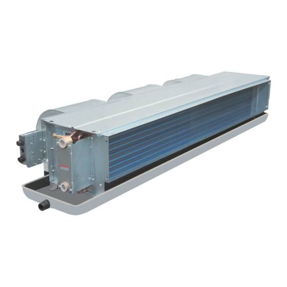
- Page 1 Engineer Data ED-FWW-V-201401A Ceiling Concealed Chilled Water Fan Coil Unit Models: FWW200 FWW300 FWW400 FWW500 FWW600 FWW700 FWW800 FWW1000 FWW1200 FWW1400 Air Flow: 340-2380m...
-
Page 2: Table Of Contents
Literature No.: ED-FWW-V-201401A Supersedes: ED-FWW-V-201310A Contents Nomenclature …………………………………………………………………………………… 2 Valve Nomenclature …………………………………………………………………………… 3 Features ………………………………………………………………………………………… 4 Specifications …………………………………………………………………………………… 5 Sound Data ……………………………………………………………………………………… 6 Air Flow vs ESP Curve ………………………………………………………………………… 7 Operating Limits ………………………………………………………………………………… 8 Water Flow Rate/Pressure Drop Chart ……………………………………………………… 9 Outlines and Dimensions………………………………………………………………………... -
Page 3: Nomenclature
Nomenclature FWW 200 V C 3 R C X - A 0 A E Sales Region: E: Export Power Supply: A: 220V~/50 Hz Other Feature Codes Material of Drain Pan Filter: X: no filter F: 8mm nylon filter A: 8 mm aluminum filter Return Air Plenum: C: without return air plenum B: back return air plenum... -
Page 4: Valve Nomenclature
Valve Nomenclature FWW - 2V 4 Y B R A E E-Export U-Stick "Made In China" Power Supply: A-220-240V/1Ph/50Hz K-208-230V/1Ph/60Hz Pipe Connection R-for Right hand unit L-for Left hand unit Valve Type B-with Ball Valve X-without Ball Valve Strainer Type Y-with Y-Strainer X-without Y-Strainer Union Size... -
Page 5: Features
Features Compact ■ Light-weighted, good-looking appearance, and compact and solid structure. ■ 235 mm height, allowing installation on the ceiling with a limited space. Low-noise ■ Low-noise motor for driving the low speed fan with a wide impeller; strictly tested before delivery. ■... -
Page 6: Specifications
Specifications General Data FWW-VC FWW200VC FWW300VC FWW400VC FWW500VC FWW600VC FWW700VC FWW800VC FWW1000VC FWW1200VC FWW1400VC MODEL 1020 1170 1360 1700 2040 2380 HIGH 1000 1200 1400 1115 1394 1673 1952 MEDIUM Flow 1148 1020 1190 EXTERNAL Pa/in.wg 12,30,50/0.05,0.12,0.20 STATIC PRESSURE 2220 3300 4260 5050... -
Page 7: Sound Data
Components Data FWW-VC FWW200VC FWW300VC FWW400VC FWW500VC FWW600VC FWW700VC FWW800VC FWW1000VC FWW1200VC FWW1400VC TYPE GALVANIZED STEEL DOUBLE STAGE IMPELLER CENTRIFUGAL (BLADE: FORWARD) QUANTITY MATERIAL GALVANIZED STEEL DRIVE DIRECT DRIVE DIAMETER 5.904 150/200/240 LENGTH 5.91/7.87/9.45 TYPE SINGLE PHAZE BALL BEARING CAPACITOR RUNNING MOTOR QUANTITY IP/INSULATION GRADE... -
Page 8: Air Flow Vs Esp Curve
Air Flow vs ESP Curve ESP, 12Pa FWW1200 FWW1000 FWW800 FWW700 FWW600 FWW500 FWW400 FWW300 FWW200 ESP, Pa ESP, 30Pa FWW1200 FWW1000 FWW800 FWW700 FWW600 FWW500 FWW400 FWW300 FWW200 ESP, Pa ESP, 50Pa FWW1200 FWW1000 FWW800 FWW700 FWW600 FWW500 FWW400... -
Page 9: Operating Limits
Operating Limits Operating Limits FWW-V Water Circuit Max. Water side pressure 1.6MPa Min. Entering water temperature 3ºC (cooling) Power supply Operating voltage limits ±10% Volt Operating frequency limits ±2Hz... -
Page 10: Water Flow Rate/Pressure Drop Chart
Water Flow Rate/Pressure Drop Chart FWW-VC WATER PRESSURE DROP CURVE(3 Rows) FWW600VC FWW700VC FWW500VC FWW300VC FWW400VC FWW200VC FWW1200VC FWW800VC FWW1000VC WATER FLOW m... -
Page 11: Outlines And Dimensions
Outlines and Dimensions WITHOUT PLENUM Number Model Number Model Of Fans Standard Long Standard Long Of Fans Drain Pan Drain Pan Drain Pan Drain Pan MCW200V FWW200V 402 437 MCW300V MOUNTING HOLE 4-10×16 FWW300V 592 627 MCW400V CONDENSATE DRAIN FWW400V 642 677 R3/4″... -
Page 12: Electrical Data
Electrical Data FWW-VC MODEL FWW200VC FWW300VC FWW400VC FWW500VC FWW600VC FWW700VC FWW800VC FWW1000VC FWW1200VC FWW1400VC INSULATION GRADE POWER V/Ph/Hz 220~/1/50 SOURCE RATED INPUT 12Pa POWER MOTOR RATED RUNNING 0.15 0.20 0.26 0.34 0.43 0.52 0.61 0.70 0.86 1.12 CURRENT POLES INSULATION GRADE POWER V/Ph/Hz 220~/1/50... -
Page 13: Wiring Diagrams
Wiring Diagrams Molde: FWW 800-1400 BLUE YELLOW BLACK BROWN MOTOR MOTOR CAPACITOR BLACK ORANGE FAN SPEED SWITCH BLUE (220V~ /50Hz) YELLOW BLACK BROWN MOTOR MOTOR CAPACITOR BLACK ORANGE NOTE: HF: FAN SPEED HIGH MF: FAN SPEED MEDIUM Only unit 800~1200 have fan motor2 LF: FAN SPEED LOW —... -
Page 14: Installation
Installation Receiving All units leaving the DAIKIN plant have been inspected to ensure the shipment of high quality products and reasonable means are utilized to properly pack the fan coil units to protect them in transit. Carefully inspect all shipments immediately upon delivery. When damage is visible, note this fact on the carrier’s freight bill and request that the carrier sends a representative to inspect the damage. - Page 15 Fig.2 WITH AND WITHOUT PLENUM FORM: Terminal block Ceiling access Panel with air return Discharge air Return air Fig.3 DETAIL A: EXP ANSION SCREW RECOMMENDED THE DIAMETER IS 6-8MM HANGING ROD FANCOIL FLAT WASHER Air Duct Connection Circulatory air pressure drop should be within External Static Pressure Galvanized steel air ducts are suitable Make sure there is no leak of air.
- Page 16 Valve Kit The valve kit is applied for 2-pipe system. The kit consists of (refer structure figure 0): • 2/3 way valve body is made of brass, maximum working pressure 1.6MPa. • Electric actuator has the following specifications: -Power supply: 220V±10%/50/60Hz (±2Hz) -Activation: ON/OFF •...
- Page 17 Installation 1. Install the 2-way valve kit as indicated in the pictures of figure 3. (For right pipe connection unit.) As shown as detail A, firstly take apart connector, then install ① to unit with necessary sealing material . Fix ②...
- Page 18 Insulation 1. The insulation design and materials should be complying with local and national codes and regulations. 2. Chilled water pipes and all parts on the pipes should be insulated. The flow resistance of the connecting valve/hydraulic kit assembly is obtained from the following formula: = (Q /100K △P...
- Page 19 Warning ● Daikin Industries, Ltd.’s products are manufactured for export to numerous countries throughout the world. Daikin Industries, Ltd. does not have control over which products are exported to and used in a particular country. Prior to purchase, please therefore confirm with your local authorized importer, distributor and/or retailer whether this product conforms to the applicable standards, and is suitable for use, in the region where the product will be used.