
Summary of Contents for Mahr Pocket Surf EMD-1500-311
- Page 1 P P P P P oc oc k k k k k et Sur et Sur et Sur f f f f f et Sur et Sur ® Portable Surface Roughness Gages MAHR GMBH, GERMANY • MAHR FEDERAL INC., USA...
- Page 2 Note: U.S. Patent No. 4,776,212 Product design and specifications subject to change without notice. Pocket Surf is a registered trademark of Mahr Federal Inc. ® Mahr Federal Inc. 2000 ®...
- Page 3 Specifications Measuring Ranges ....R — 1µ" to 250µ"/0,03µm to 6,35µm — 8µ" to 999µ"/0,2µm to 25,3µm — 8µ" to 999µ"/0,2µm to 25,3µm — 8µ" to 999µ"/0,2µm to 25,3µm Display Resolution .
- Page 4 PocketSurf Measurement Parameters Roughness Average—the arithmetic average height of roughness irregularities measured from a mean line within the evaluation length (L). MEAN LINE Maximum Roughness Depth (per DIN) — the largest of the 5 maximum peak-to-valley roughness depths in 5 successive sampling lengths. In the illustration below, R (DIN) = R Mean Roughness Depth (per DIN) —...
- Page 5 PocketSurf Measurement Parameters (continued) Maximum Roughness Depth — For the Evaluation Length equalling one cutoff, it is the vertical distance between the highest peak and the deepest valley within the sampling length. For the Evaluation Length equalling 3 cutoffs, it is the largest of the 3 maximum peak-to-valley roughness depths in 3 successive sampling lengths.
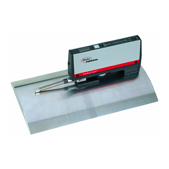
- Page 6 Pocket Surf Features 1 Digital Display 2 “Start” Button 3 Parameter Selection Switch 4 Output Connector 5 Battery Compartment Cover 6 2 “V” Feet (on bottom of unit) 7 Probe Holding Block 8 Probe 9 Protective Cover 10 Inch/Metric Switch 11 Traverse Length Switch...
- Page 7 Batter tter tter tter tter y Installa y Installa y Installa y Installa y Installation/R tion/R tion/R tion/R tion/Re e e e e placement (Alkaline onl placement (Alkaline onl placement (Alkaline onl placement (Alkaline onl placement (Alkaline onl y y y y y 1.
- Page 8 Pocket Surf Controls and Digital Display (continued) In addition to displaying the measured roughness value, the digital readout also signals other conditions: 2. Immediately after pressing and releasing the “Start” button, the readout should display the “Battery” icon and “all 8’s” (full display), indicating satisfactory battery condition for normal operation.
- Page 9 Traverse Length There are three traverse lengths available. For measuring short surfaces such as o-ring grooves, short lands and shoulders use Switch Positions 1 or 3. Nominal Number of Cutoffs/ Traverse Length Evaluation Length Switch Position .075"/2,0mm .030"/0,8mm .135"/3,5mm .090"/2,4mm .195"/5,0mm .150"/4,0mm Cutoff equals .030"/0,8mm.
- Page 10 “Closed” Position “Closed” Position “Closed” Position “Closed” Position “Closed” Position The Pocket Surf gage can be hand held or placed on a surface in any attitude; it will operate in virtually any position — horizontally, vertically, at any angle in between, even upside-down.
- Page 11 Other Probe Positions Other Probe Positions Other Probe Positions Other Probe Positions Other Probe Positions To use the gage in the other probe positions — 90°, 180° or 270°, the PocketSurf unit and probe must be carefully aligned to the workpiece surface to be measured. The base of the PocketSurf unit must be at approximately the same elevation (within ±.100"/±2,5mm) as the surface being measured, and the axis of probe traverse must be parallel to the surface being measured.
- Page 12 180° “Extended” 180° “Extended” 180° “Extended” 90° and 270° Positions 180° “Extended” 180° “Extended” In the 180° “Extended” position, the PocketSurf gage can measure flat Surfaces, large cylindrical or O.D. surfaces and inside diameters. Because there is some leeway permitted in the elevation between the base of the Pocket Surf unit and the surface to be measured, the gage can be used to measure surfaces...
- Page 13 Calibration Calibration Calibration Calibration Calibration The Pocket Surf gage is calibrated using 1. To elevate the Pocket Surf base to the Reference Specimen and the the same height as the surface of EPL-1681 Riser Plate supplied with the the Reference Specimen, place the PocketSurf Kit.
- Page 14 Calibration (continued) Calibration Calibration Calibration Calibration If the reading is within ±4 µ ",/±0,1um 5. Replace the Calibration Control Access of the value stated on the label on the Plug. bottom of the specimen*, calibration Is To check the condition of the probe within tolerance.
- Page 15 PocketSurf Probes PocketSurf Probes PocketSurf Probes PocketSurf Probes PocketSurf Probes General Purpose Probe (normally furnished) — For most surface roughness applications. 90° conical diamond stylus – .0004"/10 µ m radius for EGH-1019, .0002"/5 µ m radius for EGH-1026.† Transverse Chisel Probe EGH-1020-W1 (optional) —...
- Page 16 PocketSurf Probes (continued) Groove Bottom Probe EGH-1028 (optional) — For measuring the bottoms of “O” ring grooves, recesses and holes to depths of ¼"/6,35mm. Also used for short lands and shoulders. 90° conical diamond stylus—.0004"/10 µ m radius. The Groove Bottom Probe can only be used in the 180° “Extended” position with the Pocket Surf unit supported in a height stand or other suitable fixture;...
- Page 17 EAS-2421 VEE Fixture The EAS 2421 Vee Fixture is used for 1. Mount the Pocket Surf unit, measuring cylindrical (O.D.) parts up to with the probe in its 90° approximately 1"/25mm in diameter that position, to the fixture’s are too small to be accommodated in the Top Plate using the captive gage’s “Closed”...
- Page 18 Vee Fixture Alignment For accurate measurement with the 1. Slightly loosen the two screws that Vee Fixture, the axis of the Vee must secure the Vee to the fixture’s Bottom be aligned parallel to the axis of probe Plate just enough so that the Vee can traverse and at the proper distance be repositioned with a little effort.
- Page 19 Vee Fixture Alignment (continued) 3. Carefully adjust the position of 5. Place the Setting Pin back in the the Vee so that the probe skid Vee and place the Top Plate (with the and stylus travel precisely along Pocket Surf unit) back on the Bottom the top (“crown”...
- Page 20 Optional Accessories EAS 2426 Universal Stand The probe can be in its 90°,180° “Extended” or 270° positions. The stand’s The EAS 2426 Universal Stand 360° Column Clamp and Bracket can be is a heavy duty, fully adjustable, positioned anywhere vertically and radially multiposition comparator stand for on the column, permitting the stand to be staging the PocketSurf unit in any...
- Page 21 Optional Accessories EAS 2426 Universal Stand (cont’d) EAS-2567 Column Clamp 1. Mount the Pocket Surf unit in the & Bracket bracket on the Stand using the captive The EAS-2567 Column Clamp & screw in the base of the bracket. The Bracket is the same Column screw mates with the tapped hole in Clamp and Bracket assembly...
- Page 22 Optional Accessories EAS-2496 Height Stand 2. Position the Height Stand so that the probe is above the workpiece The EAS-2496 Height Stand is surface to be measured. Use the intended to be used on a surface Coarse Height Adjustment to bring plate or other suitably flat surface to the probe skid and stylus barely in measure workpiece surfaces ranging...
- Page 23 Optional Accessories EAS-2584 Bottom Plate The Bottom Plate accommodates cylindrical workpieces from When measuring workpiece ¼"/6,35mm diameter up to surfaces with the Pocket Surf 1½"/38mm long — long enough to span probe in the “Closed” position, the slot lengthwise and sit securely in the the EAS-2584 Bottom Plate will “V”...
- Page 24 Maintenance & Troubleshooting Gently brush the ruby skid and diamond Protection & Storage stylus tip to remove any foreign matter. To protect the gage when not in use, Clean the brush well in denatured always return the probe to its “Closed” alcohol and repeat the cleaning position and replace the Protective process until all contamination has...
- Page 25 Maintenance and Troubleshooting (continued) Error Messages If error message “E2” or “E3” is displayed on the digital readout, it usually indicates that a — Motor did not start. malfunction has occurred in the probe — Motor failed to accelerate to traverse which prevented or interfered with proper operating speed.
- Page 26 If none of the above remedies work, and an error message persists — particularly 4. Clean the bearing slot beneath the “E1” or “E4”, contact Mahr Federal Inc. Probe Mounting Block. Service Department for assistance and 5. Replace the battery. Alkaline repair information.
- Page 27 Surface Finish Marketing Group cables to interface to their devices. at Mahr Federal Inc. in Providence. Request For users who wish to make their “Pocket Surf Digital Output Data Sheet own cable, the mating connector is A-548”.
- Page 28 Also available: Shipping address EAS-2739 Vee Adaptor for returning the Pocket Surf for repair: EAS-2839 Bore Attachment (see separate instructions) Mahr Federal Inc. 1139 Eddy Street Providence, RI 02905, U.S.A. Att: Repair Department Mahr Gmbh Esslingen Mahr Federal Inc. 1144 Eddy Street Reutlinger Straße 48...
Need help?
Do you have a question about the Pocket Surf EMD-1500-311 and is the answer not in the manual?
Questions and answers