
Summary of Contents for Binks GEMS 240-3053-1
- Page 1 OPERATION MANUAL GLOBAL ELECTRONIC MIX SOLUTIONS PLURAL COMPONENT MIXING SYSTEM 240-3053-1 REMOTE COLOR CHANGE BOX INSTALLATION INSTRUCTIONS 77-3095-R1.0 (8/2015) 1 / 8...
- Page 2 IT IS THE RESPONSIBILITY OF THE EMPLOYER TO PROVIDE THIS INFORMATION TO THE OPERATOR OF THE EQUIPMENT. FOR FURTHER SAFETY INFORMATION REGARDING THIS EQUIPMENT, SEE THE GENERAL EQUIPMENT SAFETY BOOKLET (77-5300). Binks reserves the right to modify equipment specification without prior notice. 2 / 8...
- Page 3 Remote Color Change Box The remote color change box is used with the GEMS system for in-booth control of flushes, color changes, and alarm resets. For proper operation of this accessory the GEMS system requires a Zener barrier wired in series with the electrical component used in the hazardous area.
-
Page 4: Installation
Installation The remote color change box is designed to be used inside a hazardous environment, such as a spray booth, however, the Zener barrier box must remain with the GEMS control in the non-hazardous area. Mount the barrier box to the GEMS mast as described below. WARNING Installation should be performed by a qualified electrician. - Page 5 Route the cable from the box (240-3072-3) through an available strain relief and into the GEMS enclosure. CABLE NUMBER DESCRIPTION 240-3072-3 Cable, IS Remote Color Change The barrier box cable (240-3072-3) will connect to the terminals indicated here. Reroute the new harness into the enclosure and connect wires #219, 276, and 322 in the correct terminal positions as shown.
- Page 6 Mount the in-booth color change box in the desired location, TABLE C—COLOR CHANGE ensuring adequate cable length for the installation. BOX WIRING BARRIER For reference, note the barrier terminal connections for the WIRE NUMBER TERMINAL inbooth color change box. Verify the wires 4441, 4421, and 4441 DCC are connected properly according to table C.
-
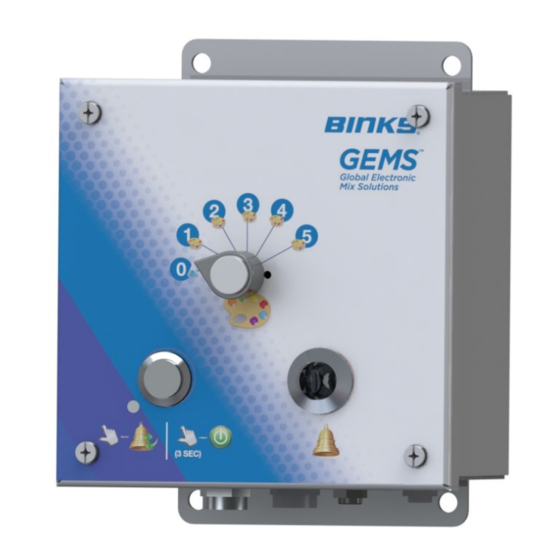
Page 7: Rotary Switch
Remote Color Change Operating Instructions Rotary Switch Push Button Pneumatic Indicator LOADING OR CHANGING A COLOR: When a color change or load is required, shut off atomizing air to the spray gun. Turn the rotary switch to the desired color number, and press the push button for 5 seconds until the flushing and / or loading process begins. -
Page 8: Warranty Policy
WARRANTY POLICY Binks products are covered by Finishing Brands one year materials and workmanship limited warranty. The use of any parts or accessories, from a source other than Finishing Brands, will void all warranties. For specific warranty information please contact the closest Finishing Brands location listed below.