Table of Contents
Advertisement
Quick Links
UB-Series
P
D
RODUCT
ESCRIPTION
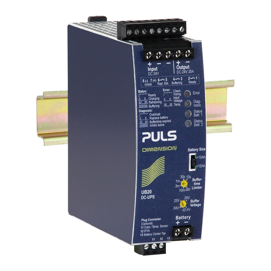
The UB40.241 is an uninterruptible power supply controller (DC-
UPS controller), which is used in combination with a 24V power
supply and an external 24V-battery pack to bridge power
failures. When the power supply provides sufficient voltages,
the DC-UPS controller charges the battery. When the power
supply voltage fails, the energy stored in the battery is released
to the DC bus in a regulated process.
A unique feature is the battery charger, which can balance two
unmatched batteries and which includes two independent
battery testers for the two 12V batteries connected in series.
This feature makes matching batteries unnecessary and allows
for precise battery charging, testing and optimized usage of the
battery capacity to achieve the longest battery service life.
The device includes various battery diagnostic functions
including a battery-low pre-warning signal that ensure a reliable
operation of the entire system. Furthermore, temperature
controlled charging extends the life of the batteries. It also
includes a selectable buffer time limiter as well as "Ready",
"Buffering" and "Replace battery" contacts. For safety and
maintenance, an inhibit-input signal is included to enable phases
without enforced buffering.
O
N
RDER
UMBERS
DC-UPS
UB40.241
Batteries
UZK24.122
UZO24.122
UZK24.262
UZO24.262
UZK24.262-E1
UZO24.262-E1
UZW24.100
UZW24.101
UZS24.100
Jun. 2020 / Rev.0.1 DS-UB40.241-EN
power supply mode at 25°C ambient, no charging and after a 5 minutes run-in time unless otherwise noted.
Standard DC-UPS unit
Battery module 24V, 12Ah
UZK24.122 w/o batteries
Battery module 24V, 26Ah
UZK24.262 w/o batteries
Battery extension 24V, 26Ah
UZK24.262-E1 w/o batteries
Connection and wiring kit
Connection and wiring kit
Sensor and center-tap board
All values are typical figures specified at 24Vdc input voltage, 40A output current in
www.pulspower.com Phone +49 89 9278 0 Germany
DC-UPS C
U
ONTROL
NIT
▪ 1-Battery-Concept - Each 12V battery is charged and monitored
separately for longest battery life, matching of batteries not
necessary
▪ Output is decoupled from the input to separate load circuits into
buffered and non-buffered sections
▪ Allows VRLA battery sizes between 12Ah and 200Ah;
"Battery Size" selector for various battery sizes
▪ 50% Extra output power for up to 5s
▪ Superior battery management for longest battery life
▪ Comprehensive diagnostic and monitoring functions
▪ "Replace Battery" signal included
▪ "Battery-Low Prewarning" signal included
▪ Selectable buffer time limiter
▪ Temperature controlled battery charging
▪ 3 Years warranty
S
-
D
HORT
FORM
ATA
Input voltage
DC 24V
Min. input voltage to start
23V
charging and to enable
battery mode
Transfer voltage to switch
22.2V
to battery mode
Internal current
3.2A / 6.2A
consumption
Voltage loss
55mV / 110mV
110mV / 220mV
Output current
50A
40A
30A
60A
Derate linearly between +50 and +70°C
Power losses
6.0W
9.9W
Temperature range
-25°C to +70°C
Size (wxhxd)
46x124x127mm
Weight
530g / 1.17lb
M
A
AIN
PPROVALS
For details or a complete approval list see chapter 19.
planned
UB40.241
24V, 40A, DC-UPS
±25%
<65Ah / ≥65Ah, incl.
charging current
Input to output,
at 20A / 40A
Battery input to output, at
20A / 40A
Below +50°C
At +60°C
At +70°C
Short term, up to 5s
At 40A in power supply
mode, full batteries
At 40A in battery mode
Without DIN-rail
IND. CONT. EQ.
planned
1/34
Advertisement
Table of Contents

Related Manuals for Puls DIMENSION UB Series

Summary of Contents for Puls DIMENSION UB Series
- Page 1 UB40.241 24V, 40A, DC-UPS UB-Series DC-UPS C ONTROL ▪ 1-Battery-Concept - Each 12V battery is charged and monitored separately for longest battery life, matching of batteries not necessary ▪ Output is decoupled from the input to separate load circuits into buffered and non-buffered sections ▪...
-
Page 2: Table Of Contents
UB40.241 24V, 40A, DC-UPS UB-Series NDEX Page Page Terminology and Abbreviations ........3 20. Regulatory Compliance ..........22 Intended Use ..............4 21. Physical Dimensions and Weight ....... 23 Installation Instructions ..........4 22. Accessories..............24 Typical Wiring Scheme ..........5 22.1. -
Page 3: Terminology And Abbreviations
UB40.241 24V, 40A, DC-UPS UB-Series 1. T ERMINOLOGY AND BBREVIATIONS DC-UPS Abbreviation for Uninterruptible Power Supply system with a DC input and a DC output. A DC-UPS utilizes batteries as back-up energy source. T.b.d. To be defined, value or description will follow later. DC 24V A figure displayed with the AC or DC before the value represents a nominal voltage with standard tolerances included. -
Page 4: Intended Use
UB40.241 24V, 40A, DC-UPS UB-Series 2. I NTENDED This device is designed for installation in an enclosure and is intended for commercial use, such as in industrial control, process control, monitoring and measurement equipment or the like. Do not use this device in equipment, where malfunctioning may cause severe personal injury or threaten human life without additional appropriate safety devices, that are suited for the end-application. -
Page 5: Typical Wiring Scheme
UB40.241 24V, 40A, DC-UPS UB-Series The enclosure of the device provides a degree of protection of IP20. A disconnecting means shall be provided for the input and the battery input of the device. The device is designed for convection cooling and does not require an external fan. Do not obstruct airflow and do not cover ventilation grid! Keep the following minimum installation clearances: 40mm on top, 20mm on the bottom, 5mm left and right side. -
Page 6: Input And Output Characteristics
UB40.241 24V, 40A, DC-UPS UB-Series 5. I NPUT AND UTPUT HARACTERISTICS The input can be powered from a regulated power supply or a similar DC source. Use an appropriately sized power supply, which can deliver the additionally required internal current consumption of the DC-UPS and the required current for charging the batteries. If a power supply with a continuous output current greater than 50A is used, a fuse or circuit breaker with 63A (B- or C-Characteristic) must be connected between the Input... - Page 7 UB40.241 24V, 40A, DC-UPS UB-Series DC-UPS. The user has to take care by himself to stay below the allowed output currents in order not to overload the unit. Output short circuit current in Corresponds to the short-circuit current of the power supply or the current power supply mode limitation of an input fuse, if installed.
-
Page 8: Batteries And Battery Charging
UB40.241 24V, 40A, DC-UPS UB-Series 6. B ATTERIES AND ATTERY HARGING The battery is not included in the DC-UPS. The battery is one of the most important parts of a DC-UPS system, which needs to be carefully selected while also paying close attention to storage, charging and environmental conditions. Select the proper battery capacity according to the required buffer time and select the right battery quality to achieve the requirements for changing intervals. - Page 9 UB40.241 24V, 40A, DC-UPS UB-Series Setting of battery size 12Ah 26Ah 38Ah 65Ah 100Ah 150Ah selector Battery voltage 2x 12V batteries in series Recommended battery sizes 12Ah - 18Ah - 35Ah - 51Ah - 81Ah - 131Ah - 17Ah 34Ah 50Ah 80Ah 130Ah...
-
Page 10: Buffer Time
The following times are typical values for a new product in combination with PULS battery modules or with batteries recommended from PULS. Due to long-term aging effects of batteries consider a buffer time reduction of 30-50% over time. The values apply for a battery temperature between 20°C and 30°C. - Page 11 UB40.241 24V, 40A, DC-UPS UB-Series Fig. 7-1 Buffer time curves, typ. B uffer C urrent Minutes Hours B uffer Time Jun. 2020 / Rev.0.1 DS-UB40.241-EN All values are typical figures specified at 24Vdc input voltage, 40A output current in 11/34 power supply mode at 25°C ambient, no charging and after a 5 minutes run-in time unless otherwise noted.
-
Page 12: Inhibit-Input
UB40.241 24V, 40A, DC-UPS UB-Series 8. I NHIBIT NPUT The inhibit-input is a feature to disable the battery mode on purpose. This can be the case when buffering should actively be stopped in order to save battery capacity and to have shorter recharging time. The inhibit-input can also be used in case of a service event, where the application must be turned off. -
Page 13: Signal Outputs
UB40.241 24V, 40A, DC-UPS UB-Series 9. S IGNAL UTPUTS Please note: If the buffering is terminated due to the deep discharge protection or due to the buffer time limiter, the last signal state is stored and displayed for another 15 minutes. Ready contact The ready contact is closed when both batteries are charged more than typical 85%, no wiring failure is detected, input voltage is sufficient and inhibit signal is not active. -
Page 14: Efficiency And Power Losses
UB40.241 24V, 40A, DC-UPS UB-Series 10. E FFICIENCY AND OWER OSSES Efficiency Typ. 99.3% Power supply mode, 40A output current, batteries fully charged Power losses Typ. 1.7W Power supply mode, 0A output current, batteries fully charged Typ. 2.7W Power supply mode, 0A output current, batteries fully charged, center tap connected Typ. -
Page 15: Front Side And User Elements
UB40.241 24V, 40A, DC-UPS UB-Series 12. F RONT IDE AND LEMENTS Fig. 12-1 Front side A Output Terminal + → Positive output - → Negative output Input Terminal + → Positive input - → Negative input Battery Terminal + → Terminal for positive battery connection - →... - Page 16 UB40.241 24V, 40A, DC-UPS UB-Series Fig. 12-2 Each battery has its own status LED. The signals are the same for both Flashing pattern for green “Status LED” batteries. (Listed in order of priorities) R eplace B at., Replace Battery, Battery or DC-UPS temperature too hot: Temp.
-
Page 17: Connection Terminals
UB40.241 24V, 40A, DC-UPS UB-Series 13. C ONNECTION ERMINALS The terminals are IP20 finger safe constructed and suitable for field and factory wiring. Input, output and battery Signal terminals (except Battery-low pre-warning terminals battery-low pre-warning) terminals Type Screw terminals Pluggable screw Push-in termination terminals Solid wire... -
Page 18: Lifetime Expectancy
UB40.241 24V, 40A, DC-UPS UB-Series 14. L IFETIME XPECTANCY The Lifetime expectancy shown in the table indicates the minimum operating hours (service life) and is determined by the lifetime expectancy of the built-in electrolytic capacitors. Lifetime expectancy is specified in operational hours and is calculated according to the capacitor’s manufacturer specification. -
Page 19: 16. Emc
UB40.241 24V, 40A, DC-UPS UB-Series 16. EMC The EMC behavior of the device is designed for applications in industrial environment as well as in residential, commercial and light industry environment without any restrictions. The device complies with EN 61000-6-1, EN 61000-6-2, EN 61000-6-3, EN 61000-6-4, EN 61000-3-2 and EN 61000-3-3. The device complies with FCC Part 15 rules. -
Page 20: Environment
UB40.241 24V, 40A, DC-UPS UB-Series 17. E NVIRONMENT Operational temperature -25°C to +70°C (-13°F to 158°F) Operational temperature is the same as the ambient or surrounding temperature and is defined as the air temperature 2cm below the unit. Storage temperature -40°C to +85°C (-40°F to 185°F) For storage and transportation Output de-rating... -
Page 21: Safety And Protection Features
UB40.241 24V, 40A, DC-UPS UB-Series 18. S AFETY AND ROTECTION EATURES Isolation resistance Min. 10MOhm At delivered condition between power port and signals, measured with 500Vdc Min. 10MOhm At delivered condition between power port and housing, measured with 500Vdc Min. 10MOhm At delivered condition between signals and housing, measured with 500Vdc... -
Page 22: Approvals And Fulfilled Or Tested Standards
UB40.241 24V, 40A, DC-UPS UB-Series 19. A PPROVALS AND ULFILLED OR ESTED TANDARDS IEC 61010 CB Scheme Certificate IEC 61010-2-201 Electrical Equipment for Measurement, Control and planned Laboratory Use - Particular Requirements for control equipment IEC 60950-1 CB Scheme Certificate planned IEC 60950-1 General safety requirements for Information Technology Equipment (ITE) -
Page 23: Physical Dimensions And Weight
UB40.241 24V, 40A, DC-UPS UB-Series 21. P HYSICAL IMENSIONS AND EIGHT Width 46mm 1.81’’ Height 124mm 4.88’’ Depth 127mm 5.0’’ The DIN-rail height must be added to the unit depth to calculate the total required installation depth. Weight 530g / 1.17lb DIN-rail Use 35mm DIN-rails according to EN 60715 or EN 50022 with a height of 7.5 or 15mm. -
Page 24: Accessories
UB40.241 24V, 40A, DC-UPS UB-Series 22. A CCESSORIES 22.1. ZM10.WALL – W ANEL OUNT RACKET This bracket is used to mount the devices on a wall/panel without utilizing a DIN-Rail. The bracket can be mounted without detaching the DIN-rail brackets. Fig. -
Page 25: Zm12.Side - Side Mounting Bracket
DC-UPS ENSOR OARD FOR The UZS24.100 enables all the benefits of the PULS 1-Battery-Concept when using individual batteries and not one of the UZK24 battery modules. This sensor board makes the use of matched batteries unnecessary and allows a precise battery charging and testing resulting in the longest possible battery life. -
Page 26: Uzk24.122 - 24V, 12Ah Battery Module
UB40.241 24V, 40A, DC-UPS UB-Series 22.4. UZK24.122 – 24V, 12AH B ATTERY ODULE The UZK24.122 battery module, recommended for load currents up to 40A, which utilizes two non-spillable maintenance-free VRLA lead-acid batteries with absorbent glass mat (AGM) technology connected in series. It is assembled with 1.5m wire leads and fusing included. -
Page 27: Uzk24.262-E1 - 24V, 26Ah Battery Module Extension
UB40.241 24V, 40A, DC-UPS UB-Series 22.6. UZK24.262-E1 – 24V, 26AH B ATTERY ODULE XTENSION The UZK24.262-E1 battery module extension utilizes two non-spillable maintenance-free VRLA lead-acid batteries with absorbent glass mat (AGM) technology connected in series. It is assembled with all wiring included. -
Page 28: Uzw24.100 - Connection And Wiring Kit
ONNECTION AND IRING The UZW24.100 is a wiring kit for batteries which are not supplied by PULS or larger sized batteries. It includes the necessary cabling and a 60cm fastening strap for fixing to the battery. The battery wiring is optimized for 26Ah batteries. -
Page 29: Application Notes
UB40.241 24V, 40A, DC-UPS UB-Series 23. A PPLICATION OTES 23.1. O UTPUT IRCUIT REAKERS Some applications require branch circuit or branch circuit conductor protection on the 24V supply voltage. Therefore, standard miniature circuit breakers (MCB’s or UL 1077 circuit breakers) are commonly used on 24V branches. MCB’s are designed to protect wires and circuits. -
Page 30: Battery Replacement Intervals
UB40.241 24V, 40A, DC-UPS UB-Series 23.2. B ATTERY EPLACEMENT NTERVALS There are two main causes for battery failures and the need for replacing them: - Random failures: Within the defined service life of a battery, random battery failures can happen. E.g. short circuit in one cell, broken cell connection, acid pollution, mechanical defects, etc. - Page 31 UB40.241 24V, 40A, DC-UPS UB-Series the temperature tracking feature of the device, the end-of-charge-voltage can be set very precisely to the required value and thereby avoiding unnecessary aging effects. - Discharged batteries: Charge retention is important to get the longest battery life. Stored batteries which are not fully charged age faster then charged batteries.
-
Page 32: Series Operation
UB40.241 24V, 40A, DC-UPS UB-Series 23.3. S ERIES PERATION A series connection for 48V applications is allowed when utilizing two individual power supplies, two DC-UPSs and two battery modules. Fig. 23-4 Wiring example for 48V serial use DC 24V, 40A DC 24V, 40A Output Output... - Page 33 UB40.241 24V, 40A, DC-UPS UB-Series Parallel use for redundancy Use two DC-UPSs with two individual power supplies, two battery modules and one decoupling module to build a redundant system. Recommendations for building redundant systems: Use separate input fuses for each power supply. Set the power supply into “Parallel use”...
-
Page 34: Troubleshooting
UB40.241 24V, 40A, DC-UPS UB-Series 23.5. T ROUBLESHOOTING The following guidelines provide instructions for fixing the most common failures and problems. Always start with the most likely and easiest to check condition. Some of the suggestions may require special safety precautions. See notes in chapter “Installation Instructions”...
Need help?
Do you have a question about the DIMENSION UB Series and is the answer not in the manual?
Questions and answers