
Summary of Contents for IRT DTR-1000
- Page 1 DTR-1000 Multi-Channel 3G/HD/SD/ASI + Gigabit Ethernet Fibre Optic Link User Manual I.R.T. Communications Pty Ltd | www.irtcommunications.com Revision 00...
-
Page 2: Revision History
DTR-1000 MULTI-CHANNEL 3G/HD/SD/ASI + GIGABIT ETHERNET FIBRE OPTIC LINK Revision History: Revision Date Change Description Applicable to: 19/12/2016 Original Issue. Firmware version ≥ 16/06/2020 OLED display Firmware version ≥ I.R.T. Communications Pty Ltd | www.irtcommunications.com Revision 00 Page 2 of 19... -
Page 3: Table Of Contents
Table of Contents: Section Page Revision History Operational Safety General Description Block Diagrams DTR-1000/16Tx+E | DTR-1000/16Rx+E DTR-1000/12Tx+4Rx+E | DTR-1000/12Rx+4Tx+E DTR-1000/8Tx+8Rx+E | DTR-1000/8Rx+8Tx+EError! Bookmark not defined. DTR-1000/8Tx+E | DTR-1000/8Rx+E Error! Bookmark not defined. DTR-1000/4Tx+4Rx+E | DTR-1000/4Rx+4Tx+E Technical Specifications Installation Pre-installation Power Earthing Rear Panel –... -
Page 4: Operational Safety
DTR-1000 OPERATIONAL SAFETY WARNING Operation of electronic equipment involves the use of voltages and currents that may be dangerous to human life. Note that under certain conditions dangerous potentials may exist in some circuits when power controls are in the OFF position. -
Page 5: General Description
+ 4-channel transmitter. All models come with the bi-directional Ethernet port. directional Ethernet port. The DTR-1000 comes as a 1RU enclosed chassis with all signal and power connections on the rear. 1000 comes as a 1RU enclosed chassis with all signal and power connections on the rear. -
Page 6: Block Diagrams
DTR-1000 Block Diagrams: BLOCK DIAGRAM DTR-1000/16Tx+E | DTR-1000/16Rx+E SIGNAL PATH DTR-1000 DTR-1000 /16Tx+E /16Rx+E IN 1 OUT 1 IN 2 OUT 2 IN 3 OUT 3 IN 4 OUT 4 IN 5 OUT 5 3G-SDI 3G-SDI IN 6 OUT 6... - Page 7 DTR-1000 BLOCK DIAGRAM DTR-1000/4Tx+4Rx+E | DTR-1000/4R+4Tx+E SIGNAL PATH DTR-1000 DTR-1000 /8Tx+8Rx+E /8Rx+8Tx+E IN 1 OUT 1 IN 2 OUT 2 IN 3 OUT 3 IN 4 OUT 4 IN 5 OUT 5 3G-SDI 3G-SDI IN 6 OUT 6 IN 7...
- Page 8 DTR-1000 BLOCK DIAGRAM DTR-1000/4Tx+4Rx+E | DTR-1000/4Rx+4Tx+E SIGNAL PATH DTR-1000 DTR-1000 /4Tx+4Rx+E /4Rx+4Tx+E IN 1 OUT 1 IN 2 OUT 2 3G-SDI 3G-SDI IN 3 OUT 3 HD-SDI HD-SDI IN 4 OUT 4 SD-SDI SD-SDI IN 5 OUT 5 IN 6...
-
Page 9: Dtr-1000/4Tx+4Rx+E | Dtr-1000/4Rx+4Tx+E
Dimensions 482 x 44.5 x 310 mm. Ordering DTR-1000/16Tx+E DTR-1000 configured as a 16-channel transmitter only + Ethernet. DTR-1000/16Rx+E DTR-1000 configured as a 16-channel receiver only + Ethernet. DTR-1000/12Tx+4Rx+E DTR-1000 configured as a 12-channel transmitter/4-channel receiver + Ethernet. DTR-1000/12Rx+4Tx+E DTR-1000 configured as a 12-channel receiver/4-channel transmitter + Ethernet. -
Page 10: Installation
Any of the three power inlets may be used independently, or together for power supply redundancy. NOTE: There is no ON/OFF switch. The DTR-1000 will power on as soon as an external power source is applied. Earthing: The frame is earthed via the AC mains input signal earth being connected to the chassis. -
Page 11: Alarm
16 optical transmit/receive digital video signals + bi-directional Ethernet traffic depending on the model of DTR-1000 unit. As such, optical laser outputs are multiplexed together. Avoid direct exposure to the eyes. A dust cap is included for when unit is not connected to an optical fibre. -
Page 12: Rear Panel - Signal Connections
Rear Panel - Signal Connections: The DTR-1000 is designed to be operated as a pair, though in reality they will also work into other devices that use either an internal or external CWDM optical MUX/DeMux, at the correct wavelengths, such as IRT’s single or multi-channel Eurocard and openGear®... -
Page 13: Dtr-1000/8Tx+8Rx+E | Dtr-1000/8Rx+8Tx+E
Ethernet DTR-1000/12Tx+4Rx+E Rear Panel Signal Connectors: DTR-1000/12Rx+4Tx+E Rear Panel Signal Connectors: The DTR-1000/8Tx+8Rx+E and DTR-1000/8Rx+8Tx+E models are designed to operate together as a pair. They form an 8-channel forward, 8-channel reverse fibre link with bi-directional Ethernet. IN 1 OUT 1... -
Page 14: Dtr-1000/4Tx+4Rx+E | Dtr-1000/4Rx+4Tx+E
DTR-1000 The DTR-1000/8Tx+E and DTR-1000/8Rx+E models are designed to operate together as a pair. They form an 8-channel, single direction, fibre link with bi-directional Ethernet. IN 1 OUT 1 IN 2 OUT 2 8 Tx IN 3 OUT 3 8 Rx... -
Page 15: Operation
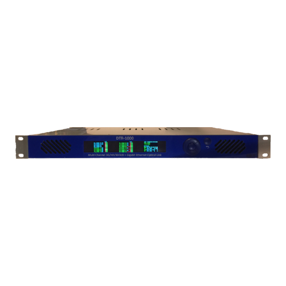
DTR-1000 OPERATION The DTR-1000 operation is essentially the same for all models of units, so a generic description will be given, with differences explained where required. Front Panel Display: The displays on the DTR-1000 are mostly self explanatory. The left and middle display show channel status including whether the channel is a transmitter or receiver and the detected signal type. -
Page 16: Front Panel Window Navigation
With the DTR-1000 connected via the Control port to an Ethernet system, using a standard web-browser enter the IP address of the DTR-1000 in the address bar to directly access and monitor the DTR-1000. Ensure that the Ethernet system allows access on the same Gateway Address. The following screen is displayed:... - Page 17 1310nm Channel_15 Rx 476 1290nm Channel_16 Rx 588 1270nm DTR-1000/8Tx+8Rx+E Version 1.3 IP Address 192.168.1.100 Mac Address FF-FF-FF-FF-FF-FF Index Temperature is measured in degrees Celsius. The power levels are indicative levels as reported by the laser and detector modules. These reading are...
-
Page 18: Maintenance & Storage
DTR-1000 MAINTENANCE & STORAGE Maintenance: Ensure that front panel fan inlets are free from dust else fan operation may be impinged and damage to laser and/or detector modules, or internal components, may occur due to excessive heat build up. Care should be taken to ensure that all connectors are kept clean and free from contamination of any kind. This is especially important in fibre optic equipment where cleanliness of optical connections is critical to performance. -
Page 19: Warranty & Service
For situations when “No Fault Found” for repairs, a minimum charge of 1 hour’s labour, at IRT’s current labour charge rate, will apply, whether the equipment is within the warranty period or not.
Need help?
Do you have a question about the DTR-1000 and is the answer not in the manual?
Questions and answers